If someone’s first question about a paramotor is, “How much does it weigh?”, I immediately know that this person is not an experienced pilot. Its geometry is much more important than kilograms and horsepower. –Miro
Welcome to “Insights into Paramotor Geometry”. This is the first part of a complete series where we will cover every aspect of paramotor construction and design. By the end of this, you will be able to make your own judgment and decision: What is the best paramotor you?
In “Top Gear”, the famous TV show where they test fancy sports cars, they don’t solely judge vehicles based on their horsepower, acceleration, and quarter-mile times. What is more important is how these cars truly feel when you drive. It’s the same with paramotors. It’s not about weight and horsepower, but how they feel. So in fact, it’s about their geometry. Geometry is what influences how it feels in the air, how it turns, how it ground handles, how easy it is to get in and out of the seat, how well it handles turbulence, and how much fun you’re going to have when you flip it around. Many don’t realize that a paramotor’s geometry can also influence its speed in flight. Even with the same glider, the same engine, and the same pilot, one paramotor can fly faster than another. Luckily, we can predict how a paramotor is going to act and feel in the air just by looking at it. Its geometry defines this.
There are over 40 parts to this series where we will cover every aspect of paramotor construction. By the end, you will be able to decide which is the best paramotor for you is. You will learn that there is no such thing as the “best paramotor” which is perfect for everyone. Each pilot has their own needs and priorities, the first of which is flying style.
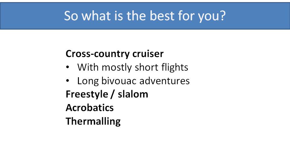
In this series we will refer to these flying styles:
- Local cross-country flying (probably most pilots)
- Adventure cross-country flying and bivouacking
- Freestyle and slalom
- Acrobatics
- Thermalling with paramotors
In each part, we will identify the advantages and disadvantages of specific paramotor designs based on these categories. We will try not to be biased and will show that a SCOUT with a Vittorazi Moster Plus is not necessarily the ideal paramotor for all pilots.
Let’s start with the most important aspect of paramotor design, and that’s its suspension.
Suspension is where you find the largest differences between paramotors, and in my opinion, it is the most important characteristic of a paramotor. It defines handling and the fun you have in the air. It also defines comfort, both in the air and on the ground. It has safety implications, as well. –Miro
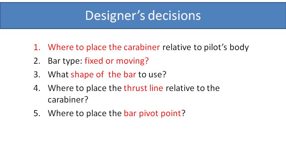
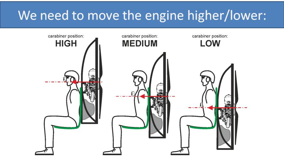
There are a few decisions that a paramotor designer needs to make regarding suspension. The first is the position of the carabiners relative to the pilot’s body. On high-suspension paramotors, the carabiners are up around the pilot’s ears. On low-suspension paramotors, they are down towards the pilot’s waist. On mid-suspension paramotors, they are closer to the pilot’s armpits. Also, the suspension bars can either be fixed or moving. Between these two aspects, there can be several solutions, and each of these has benefits and disadvantages that we will examine in depth throughout this series.
Beyond this, there are a few more decisions that a paramotor designer needs to make regarding its suspension:
- The shape of the suspension bars
- Where to place the thrust line relative to the carabiners
- If using moving bars, where to place their pivot points

Let’s look at each design choice and the effect it has on a paramotor.
- The positioning of the carabiners relative to the pilot’s body defines the in-flight comfort, how much weight-shift authority there will, be and how it handles turbulence
- Using fixed vs. moving bars influences weight-shift authority and ground handling
- The shape of the bars helps in-flight comfort
- The thrust line relative to the carabiners controls the pitch stability under power and ground handling
- The location of the pivot point for moving bars helps the speed bar behavior
As you can see, suspension is a complex issue that we will dive into in the ensuing parts of the series.
Let’s start with weight-shift authority which is the most influential. First, we’ll explain why we need weight-shift, and then we will go on to compare the various suspension systems and how they correlate with weight-shift authority.
After we cover the other aspects of suspension systems and their effects, we will show a full comparison to give you the complete picture.
I must warn you that I am biased. I’m a big advocate of weight-shift steering in paramotors. I know many pilots who have switched to weight-shift paramotors and they will never go back. Yet, there are many pilots who have never tried it, so give me a chance to convince you. –Miro
“Look, Lean, Pull!”
This is what paragliding instructors will tell you. This is how they core thermals. It means to look towards the side you want to turn, lean to that side, and then gradually pull the brake. With paramotors, it’s pretty much the same. You can do it with a little bit of leg work and by leaning over the bar. Leg work is just raising one leg and pressing the other one down. Leaning over the bar is just moving your body over the bar and shifting your center of gravity closer to one side.
Many of today’s pilots are flying smaller gliders with 2-D steering that are quite agile, and they can skip the weight-shift and just pull the brake. But turning with weight-shift is much more efficient than turning without. In effect, with weight-shift, you have more turning authority. You’re using two steering inputs instead of one. So, you could use half of the brake input to achieve the same turn or get a much tighter turn with the same brake input.
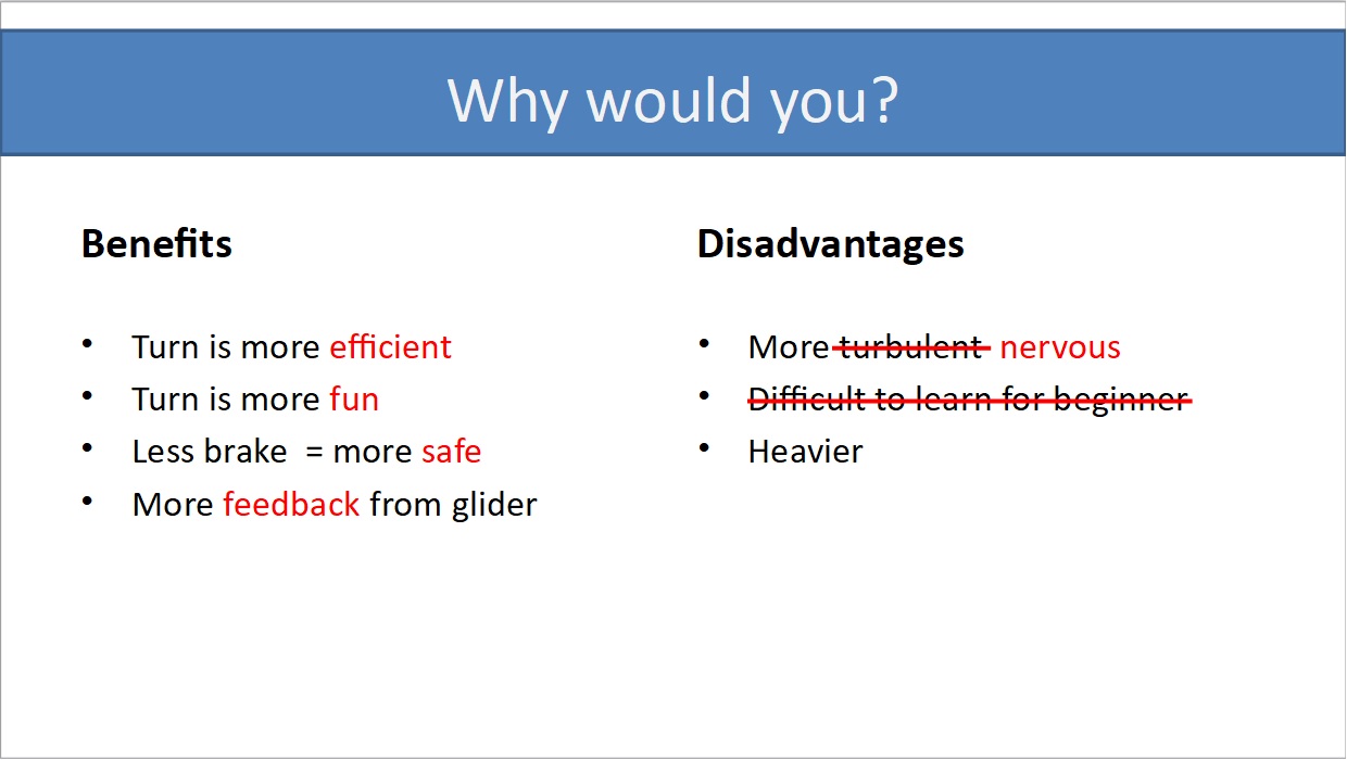
Here is a summary of benefits and disadvantages of weight-shift steering. Regarding benefits, primarily, turns are more efficient. When you pull less brake, you are turning with less drag. Your glider is closer to the ideal profile and flies closer to its most efficient way. Secondly, turns are more fun. This is a bit tricky to explain…you just need to try it. When you lean to the side and you feel the pressure in your body, it feels much more engaging. It’s like leaning into a turn on a motorcycle. It’s also safer. The less brake you pull, the further away the glider is from stalling or spinning. Finally, you get more feedback from the glider. You feel more of the turbulence and what’s happening to your glider. This gives you a chance to react and compensate earlier.
Some pilots believe that flying a weight-shift paramotor exposes them to more turbulence, but it’s not true. If you fly into turbulence, it’s there regardless of what paramotor you are flying. The only difference is that, with a weight-shift paramotor, you feel more feedback from the glider and the paramotor doesn’t hide it from you. The turbulence will make the glider feel twitchy and bumpy which may make the pilot feel more nervous. Having said that, it’s a personal preference and we like the “sporty” feeling where you can feel what the air is doing.
There are arguments that weight-shift paramotors are more difficult to learn for beginners. We disagree on this point as well, because having more feedback from the glider during takeoff or in-flight will make it easier for the for the pilot to understand and feel the glider. In the end, we believe the student will learn more quickly.
It’s true that weight-shift paramotors are heavier. The bars need to be made of solid and strong material because the pilot, engine, and fuel tank is hooked onto them. So, the added strength of these bars adds some weight.
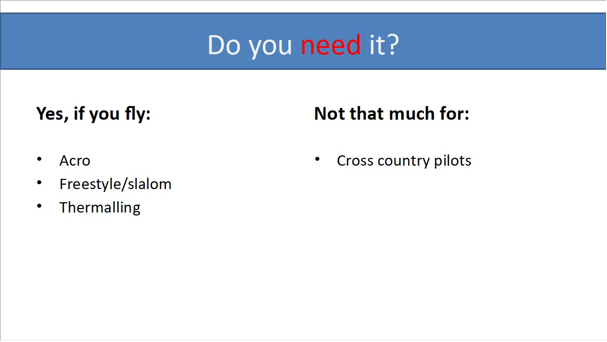
So, here’s the big question: Do you need weight-shift steering for your flying?
You absolutely need it if you are an acro pilot, fly freestyle or slalom, or do thermalling because you just need the feedback from the glider…you need to feel the glider perfectly. For cross-country pilots, it’s not as necessary. You could be happy flying a high hang-point paramotor for cross-country flights, but it still doesn’t hurt to have weight-shift ability.
So, if your flying styles overlap such that you do mostly cross-country but sometimes you do some freestyle flying with tight turns and have some fun, then you surely want to add weight-shift steering as well. Beyond this, we believe it is more comfortable, which we will cover in the ensuing chapters.
For the next chapter, we will be a bit more technical. We will compare all the suspension systems and explain how much weight-shift authority you get and why.
Click to watch videoHi guys! The last time we talked about why you want or need weight-shift on your paramator. Today, now let’s how much weight-shift authority you actually get. –Miro
Here is a slide from an earlier part that itemizes the suspension decisions that a paramotor designer must make. Let’s go through them all and see how they affect weight-shift.
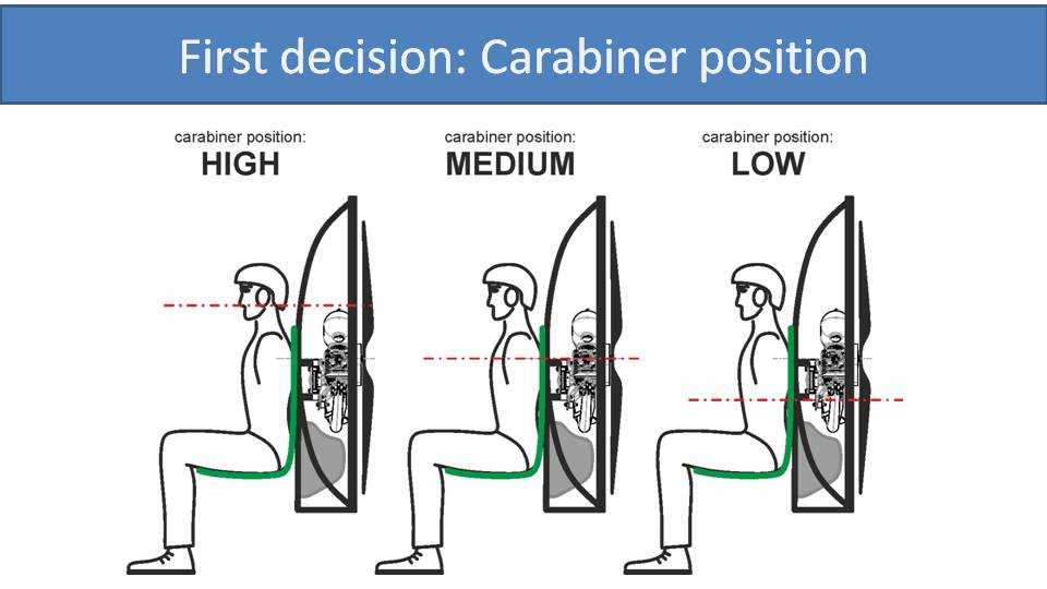
The first decision is where to place the carabiner relative to the pilot’s body, high, medium, or low.
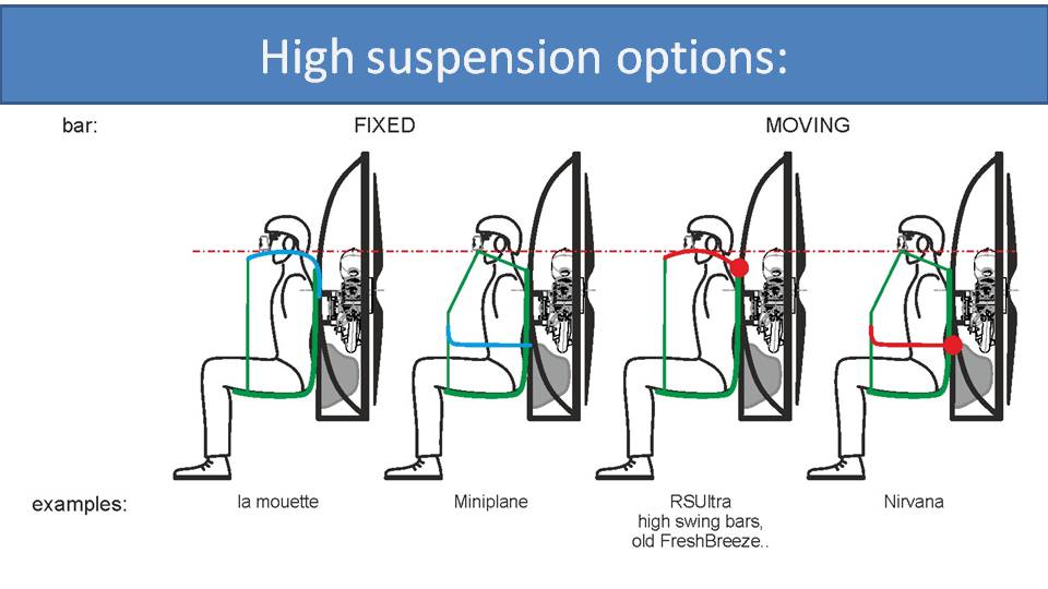
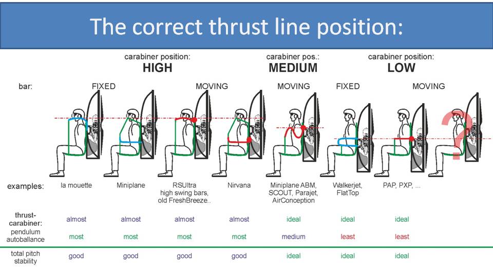
We have four high-suspension options, two with fixed bars and two with moving bars. The one on the left is a fairly “old school” solution. It’s a solid bar of metal that rises from the back up and over your shoulder. It’s similar to a coat hanger that keeps the harness in shape. Without that bar, the harness would just flop down. This design is not really used much anymore.
The second solution is more common. It’s a high-hook-in system where the carabiner is connected to a strap that goes up and over your shoulder. There is a fixed spreader bar under your shoulder that keeps the strap in position.
Then, there are variations of each of these, but with moving bars. They are attached to the frames at a pivot point, indicated by the red dot, that allows rotation and some flex in the harness.
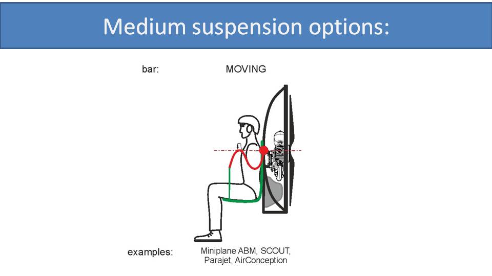
For medium-suspension designs, there is effectively only one solution on the market. This is referred to as a “gooseneck bar” that goes underneath your arm before curving up close to your chest where the carabiner is positioned. Then, it has a pivot point at the red dot where the bar can rotate for easy takeoff and maneuvering. This is the most common suspension used with paramotors, and later we’ll discuss why.
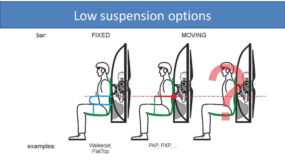
For low-suspension systems, there are primarily two options: fixed bar and moving bar. The fixed bar is a solid construction that’s attached directly to the frame, and the moving bar has a pivot point that can rotate around the red dot. In truth, there is a third option that is more complicated and not common. Consider this a teaser, and we’ll cover it in a separate part.
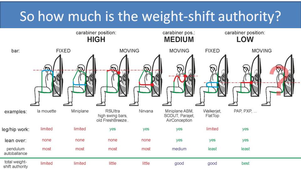
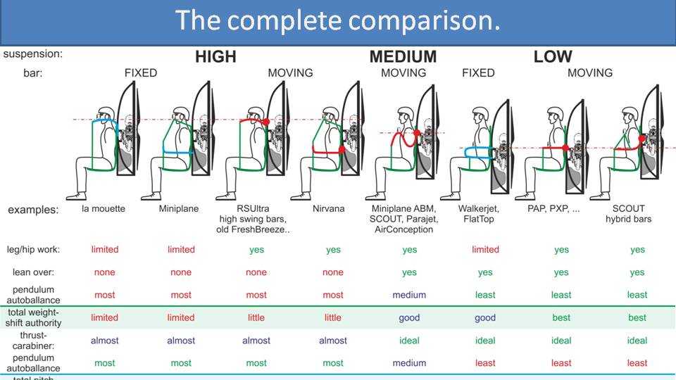
Let’s go through the full comparison of all suspension systems and how they affect weight-shift. Remember that you can impart weight-shift in two ways. The first is leg work or hip work, and the second is leaning over. If your suspension system has a fixed bar, there is no flexibility in the frame to allow leg work to alter the carabiner positions relative to each other. So, there is not much weight-shift you can do with just leg work. This is true with any fixed-bar system, high or low.
There is a lot more weight-shift authority with moving-bar systems when using leg work. As you press one leg down and raise the other, you effectively lower one carabiner and raise the other and shift the loading on the glider.
The other way to perform weight-shift is by leaning over. With high-suspension systems, bars and/or straps are up around your shoulder and head level and don’t leave you much room to lean over. So, the lower the carabiner is, the more weight-shift authority is possible. This is why the four paramotors on the left have no lean-over weight-shift authority and the three on the right have significant lean-over weight-shift authority.
The other aspect that influences your weight-shift authority on a paramotor is the pendulum auto-balance effect. Put simply, the further that an object is suspended above a point, the stronger its intention to move back to the center position. It effectively requires more weight-shift to achieve the same tilt angle of the pendulum. So, if you are suspended higher and closer to the pivot point of the pendulum, the same amount of weight-shift will cause a lot more tilt in the pendulum. Put simply on our chart, high-suspension systems have the most pendulum auto-balance fighting weight-shift, and low-suspension systems have the least.
Let’s now look at the summary of total weight-shift authority for each design. You get limited weight-shift authority with high-suspension systems, but bit better with moving bars. You get fairly good weight-shift authority with medium-suspension systems with moving gooseneck bars. And, you get the best with the low-suspension systems with moving bars.
Because we discussed how weight-shift is an advantageous tool for paramotor pilots, this leads us to the conclusion that low-suspension systems with moving bars are the best option. However, there are other considerations that we will discuss in the next few parts. Also, there is a mistake in at least two of these pictures. Continue with the series to learn more.
Click to watch videoWhen we did the big comparison of various suspension systems regarding weight-shift authority, we said there are at least two pictures with a mistake. Let’s add a bit of power and find out. –Miro
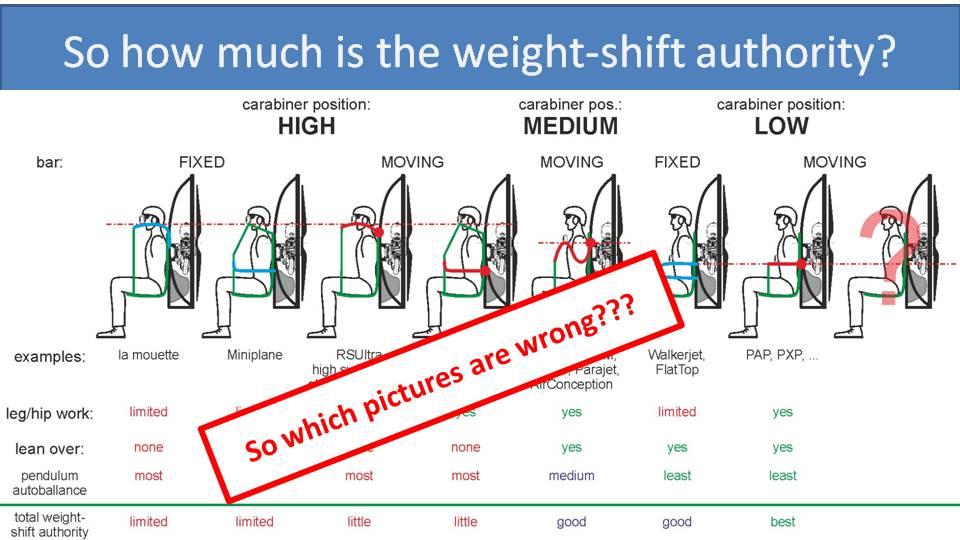
At least two pictures are wrong in this lineup. To find out, we will discuss the fourth decision that a paramotor designer needs to make when designing paramotor suspensions: Where to place the thrust-line relative to the carabiners?
The ideal position of the thrust-line is directly in line with the carabiners, where the paramotor will pivot relative to the glider. If we apply thrust above this pivot point, the paramotor will pitch forward. If we apply below, it will pitch backward. But, if we apply thrust in line with the carabiners, the paramotor won’t pitch either direction.
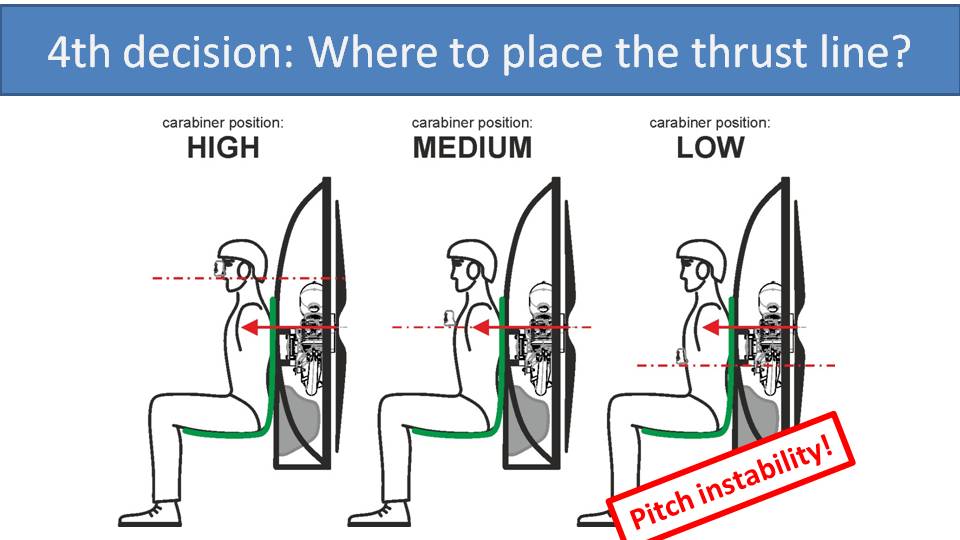
Let’s see how it works with these paramotors.
With the high-suspension system, where the carabiners are higher than the thrust line, the pilot will be pitched backwards under full power. With the medium-suspension system, where the thrust line is in line with the carabiners, the pilot won’t be pitched backwards or forwards under full power and will just start to climb in an efficient manner. With the low suspension system, where the carabiners are below the thrust line, the pilot will be pitched forwards under full power. Having said this, due to gravity, the weight of the pilot will resist the pitching force caused by the imbalance to a degree.
Is it possible to fix this unwanted behavior? For the low-suspension system, the solution is to move the engine, propeller, and cage down to be in line with the carabiner position. We will also get a beautiful crumple zone beneath the pilot. For the medium-suspension system, there is no need to make any adjustment. For the high-suspension system, we could raise the engine, propeller, and cage up to the carabiner position. This would be great for flying, but horrible for taking off. Imagine what it would feel like to have 80kg of thrust at your neck. It would just push your head into the ground, and another pilot bites the dust.
Let’s return to our line-up of suspension systems from Part 2. We have now placed the engine, propeller, and cage lower for the low-suspension systems. On the high-suspension systems, we have placed them a bit higher, though not all the way. This means that the thrust line is in an ideal position for medium and low-suspension systems. But, it is less than ideal for the high-suspension systems. Thankfully, the pendulum auto-balance effect helps to mitigate the issue in those four designs.
In summary, medium and low-suspension systems have ideal pitch stability, but it’s acceptable on high-suspension systems. Don’t jump to any conclusions just yet. Yes, it looks like a winner for the low-suspension system with moving bars, but there is a fifth decision that a paramotor designer needs to make. We now need to discuss where to place the pivot point for the bars. To determine the ideal position, we need to add some speed by pushing the speed bar.
Click to watch videoIn the last chapter, we added power to our suspension systems. This time let’s push the speed bar. The results will be surprising. –Miro
Part 6: Speed Bar and the Suspension
When you push the speed bar, you apply fly force with your feet to extend the speed bar and fully accelerate your glider. But, when you push the speed bar, you need to push off of something. Your upper back pushes up against the paramotor frame for you to extend the speed bar.
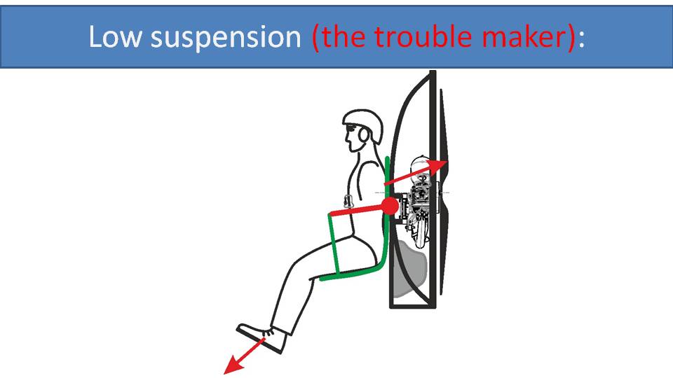
Let’s see what happens on a low-suspension paramotor, which is the troublemaker. Its bars’ pivot points are low. So, when you push with your upper back to extend the speed bar, it causes the paramotor to pitch backwards.

If the propeller is tilted backwards, then the thrust-line pushes you upwards. This is unwanted behavior. It makes you lighter, decreases the wing loading, and you fly slower than you would otherwise. It is also less efficient as some of the thrust is just lightening the pilot. This is not what you want when pushing the speed bar.
Apart from the lower speed, there are also some safety issues, which we will cover later. Please keep in mind that this issue is only valid for low-suspension paramotors with moving bars. With fixed bars, nothing happens because the frame provides a rigid platform to push from.
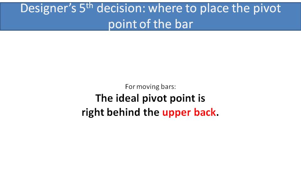
So, what’s the solution? We simply need to move the bars’ pivot points up around the upper body of the pilot. Therefore, if you push back with your upper body, you’re pushing right into the pivot point and the paramotor will not lean back.

This is how the gooseneck bars are designed with a medium suspension system. If the pilot pushes their upper body against the frame, it will be directly in-line with the bars’ pivot points. The paramotor will not pitch forwards or backwards.
There is one more thing to consider, which is your center of gravity when you push the speed bar. This is especially true when you extend your legs forwards instead of down. Your center of gravity will be shifted forward a bit causing you to lean a little forward.
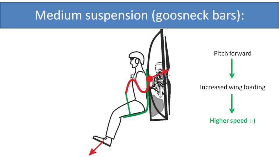
Then, part of the thrust will push you down a bit, increasing the wing loading, and flying you faster. Since this is what we want when we push the speed bar, it’s desirable behavior.
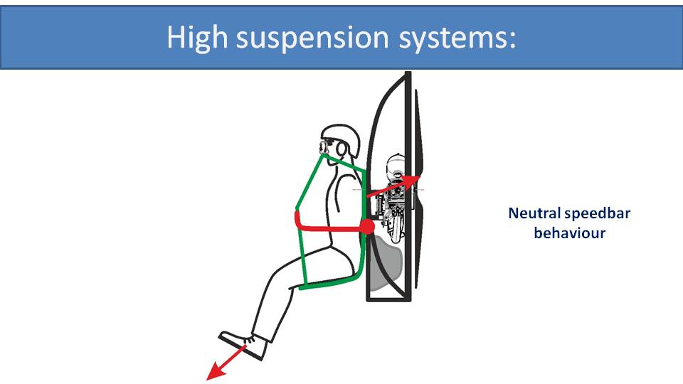
High-suspension systems behave neutrally because all the straps are highly tensioned. This makes the harness and frame rather rigid. So, there is no tendency to tilt backwards when pushing the speed bar. There is also not much tendency to tilt forwards when your center of gravity shifts forward because of the pendulum auto-balance effect. The suspension point is just too high for the shift in center of gravity to have a significant effect.
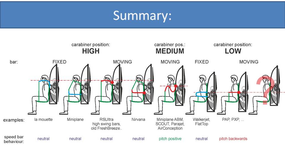
So, let’s do the final speed bar comparison with all the suspension systems lined up. High suspension systems behave neutrally, regardless of fixed or moving bars. Medium-suspension systems, with gooseneck bars, pitch forwards. Low-suspension systems with fixed bars are neutral because the harness’ geometry doesn’t change. And low-suspension systems with moving bars will pitch backwards, which is unwanted behavior.
So, we have added power to our paramotors, and we have pushed the speed bar. Now, it’s time to go back to the ground. In the next part, let’s talk about ground-handling and running with a paramotor.
How does a paramotor’s suspension design influence ground-handling and running with it? It’s surprisingly significant. –Miro
Part 7: Ground-Handling and Running
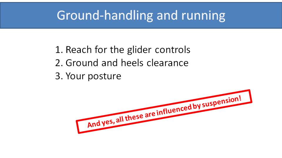
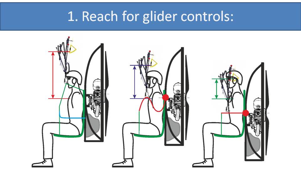
There are few aspects of a paramotor’s suspension that influence your ability to ground-handle and run with it. It can affect your reach for the glider controls, your ground clearance, and your posture.
Regarding your reach for the glider controls, we’re not just referring to the brake toggles. You also need to be able to pull your As on a reverse launch, pull your As on a forward launch, and reach for the brakes and risers on your final run while taking off. On high-suspension paramotors, your As, Ds, and brake toggles are positioned quite high, which makes it difficult to reach for them on both forward and reverse launches, as well as your final run. The best position is on low-suspension systems. All your glider controls are easily in reach and in view, which is similar to paragliding harnesses. With medium-suspension systems, the gooseneck bars drop for easy launches. Then, the controls are still visible and within reach as the glider pulls the bars up during your final run.
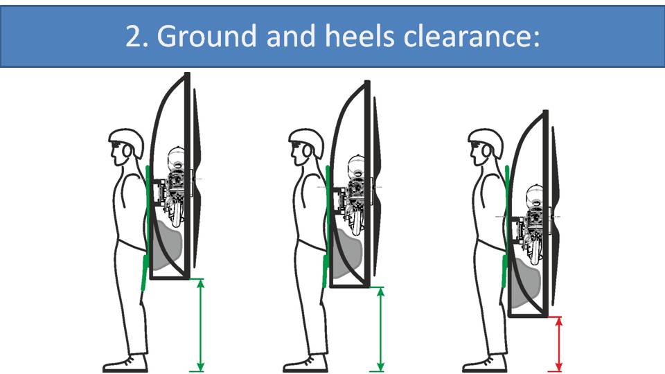
The higher the paramotor is on your back, the more clearance there is for your legs to run. With more clearance, you can run faster and achieve a faster takeoff speed. Slow takeoff speeds lead to failed launches, especially in nil wind conditions. And when ground-handling or landing, the extra ground clearance reduces the chances that the paramotor hits the ground if you slip or stumble.
With high and medium-suspension systems, the paramotor is mounted fairly high on your back. It depends on the details of the harness design, but if done well, you will have enough clearance. With low-suspension paramotors, the cage’s position is much lower, as explained in Part 5. So, there is a higher chance that your legs will be impeded by the frame when running quickly or the frame may hit the ground if you stumble.
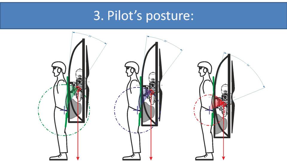
The final aspect that influences ground-handling and running is your posture while wearing the paramotor. With the weight of a paramotor on your back, it’s impossible to stand completely upright. You need to lean forward to move the center of gravity of the paramotor to be above your heels. This is much easier if the load is positioned high on your back because the angle you need to lean to move the paramotor over your heels is much less. This is what mountaineers do when they load their backpacks. They try to position heavier objects high in their pack and high on their body, so they only need to lean forward a little.
Let’s look at an extreme example with a low-suspension on the right to see what happens. Since the paramotor’s weight is down near the pilot’s waist, they must lean forward much more to position it above their heels. You can see that the lean angle is twice as much as the high-suspension paramotor.
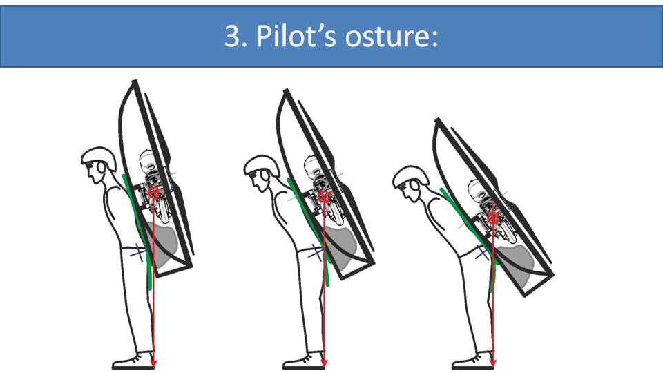
Here we have each pilot leaning forward to compensate for the paramotors on their backs. With low suspension paramotor on the right, the pilot will need to lean forward the most to get the paramotor’s center of gravity above their heels. Just by looking at these pictures, it’s easy to see that running and ground-handling with the paramotors on the left will be much easier than with the one on the right.

Let’s go through our final summary. The reach for the glider controls is best with low-suspension, good with medium-suspension, and too high with high suspension systems. This is important. Reach for glider controls is crucial for launching. Ground clearance is the best with high-suspension and medium-suspension systems, where the paramotor position is similar. The least amount of ground clearance is with low-suspension systems. The pilot’s posture is good with high and medium suspension systems and most demanding with low-suspension systems.
Overall, the medium-suspension system is best for ground-handling, and there will be compromises for low and high-suspension systems.
Let’s talk about your comfort in flight. Obviously, the harness design and build quality is a major influence, but the suspension has some implications as well. –Miro
Part 8: Comfort in Flight
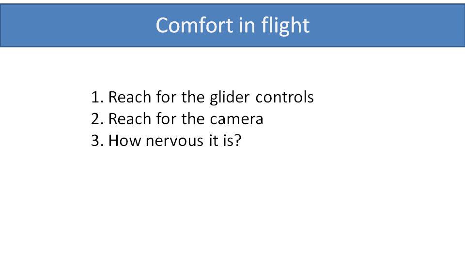
The design of a paramotor’s suspension system influences your comfort in the air in three ways:
1. Your reach for the glider controls
2. Your reach for your camera
3. How nervously it feels in turbulence
Let’s start with your reach for the glider controls, especially the brakes. With high-suspension systems, the brake toggles are rather high. This is especially true with the trimmers out. Then your arms will be way up in the air like a chimpanzee, which is uncomfortable and tiring. With low-suspension systems, your arms are in a natural position and it’s the most comfortable solution. On medium-suspension systems, your arms will be a bit higher, but it’s still comfortable for long flights.
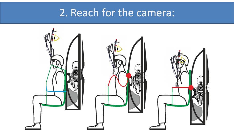
Regarding your reach for your camera, this is merely an example for your freedom of movement within your harness. With high-suspension systems, there are high-tension straps that run beside your ear up to the carabiners and then down towards your thighs. They are under a lot of tension which makes them rigid and immovable. They impede your freedom of movement and make it difficult to reach around and use your camera. Freedom of movement is much better with low and medium-suspension systems because the bars are under your armpits or down by your waist. Also, the carabiners and risers are close to your body making them easy to reach around to do anything you need. Even so, it’s easy to pull your arms back within the carabiners to pull start your motor, fuss with your jacket zipper, or do anything else close to your body.
The third way a paramotor’s suspension system affects your comfort in flight is how nervous and twitchy it feels in turbulence. There is no weight-shift authority without glider feedback. It goes hand in hand. So, the more weight-shift authority you have, but more gilder feedback you get. As we have noted in earlier parts, we are big fans of weight-shift authority. We also believe that feedback from your glider is good for your safety because it’s critical for active piloting. Having said that, this discussion is about your comfort in flight, and a twitchy paramotor is discomforting.

Here is the lineup for our final comparison. Regarding your reach for your glider controls, the brake toggles are just too high with high-suspension systems. Medium-suspension systems have good reach for the glider controls, and low-suspension systems are the most comfortable. With the reach for your camera and freedom of movement, it is limited with high-suspension systems and good for medium and low-suspension systems. The paramotor’s nervousness and twitchiness in turbulence is the calmest with high-suspension systems and the most active with low-suspension systems.
Overall, we believe that the best option for comfort in flight is the medium-suspension system with gooseneck bars. But comfort is pretty good with low-suspension systems and the high-suspension systems are the least comfortable.
We have now covered nearly every aspect of paramotor suspension designs. We’ve covered handling, added power, pushed the speed bar, did some ground-handling and talked about comfort in the air. Before we do a big overall comparison, it’s time to reveal the mystery suspension design, which we will describe in the next part.
We’re almost finished talking about suspension systems in our paramotor geometry series. We have covered weight-shift, pitch stability, speed bar behavior, ground-handling and in-flight comfort. Before we do the big final comparison and make some conclusions, we need to reveal the mystery suspension design. –Miro
Part 9: The Mystery Suspension System
From the beginning, we have been telling you that we’re big fans of weight-shift steering, because it’s more efficient, safer, and more fun. Low-suspension systems have the most weight-shift authority, but there is no free lunch.
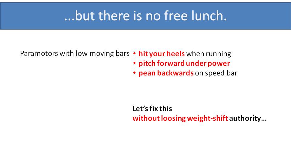
They are accompanied by some disadvantages. First, on low-suspension systems, the paramotor hangs lower on your back. So, your legs might hit the cage while ground-handling, and the cage is more likely to hit the ground if you stumble. Second, if not done properly, they tend to pitch forward under full power. The speed bar behavior is suboptimal, as well, as it can pitch the paramotor backwards. Medium-suspension systems with gooseneck bars alleviate the disadvantages, but some weight-shift authority is compromised.
Is there a design that can have it all?
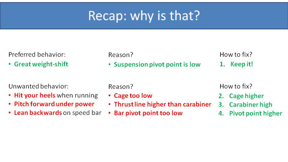
Let’s do a quick recap. The reason why low-suspension systems have such great weight-shift authority, is that the suspension’s pivot points (the carabiners) are low compared to the pilot’s center of gravity. So, we want to keep that. But there is some unwanted behavior, like hitting your heels while running because the cage is too low. So, we need to raise the cage. But that will cause the paramotor to pitch forward under power because the thrust line is now higher than the carabiners, so we’ll need to reposition carabiners up with the thrust line while keeping the “low-suspension behavior”. Finally, low-suspension paramotors tend to lean backwards when pushing the speed bar because the bar’s pivot point with the frame is too low. So, we also need to raise the bars’ pivot points. Let’s explain how we can keep the low suspension system and get rid of its disadvantages.
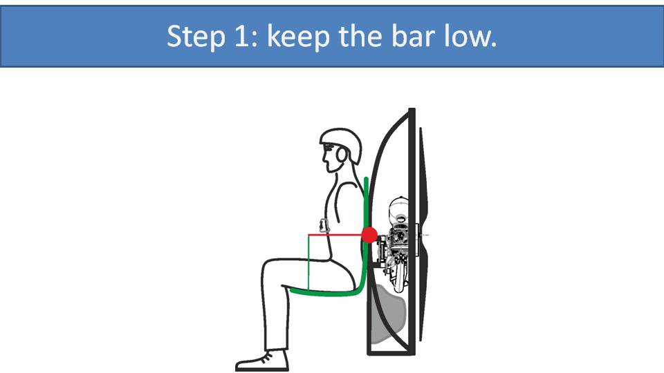
First, we will need to keep the bar low in the standard low suspension moving bar setup. The cage is way too low, so let’s move it upwards.
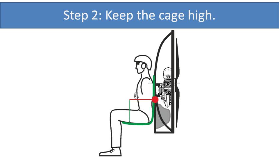
Now we face some trouble with the thrust line being above the carabiners. This would cause pitching forward as you add throttle.

What if we raised the carabiners with an extension strap? Unfortunately, this doesn’t help as it just acts like longer risers and the pivot point is right back down on the bars. Really what we want is for the left/right pivot point to be at the bars for good weight-shift authority and the forward/backward pivot point to be up at the thrust line for good pitch stability.
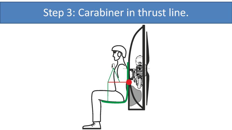
The way to solve this is by using a triangle strap. With this triangle strap, the carabiners are in the same position as with gooseneck bars. This triangle strap provides a lot of rigidity in the forward/backward direction. When you add throttle, the triangle will retain its shape and the paramotor will not pitch forward or backward, just like with gooseneck bars. The thrust is transferred directly into the carabiner.
Because the strap is connected down at the bar, it can sway left and right as one with the riser. So, the pivot point for left/right movement is down with the bar like a normal low-suspension system, and you have amazing weight-shift authority. We have now combined the weight-shift authority of low-suspension systems with the pitch stability of the gooseneck bars.
We still need to fix the unwanted speed bar behavior of low suspension systems. When you push the speed bar, you lean with your upper back against the frame. If the bars’ pivot points are lower than your upper back, then it will cause you to lean backwards. This fix is quite simple.
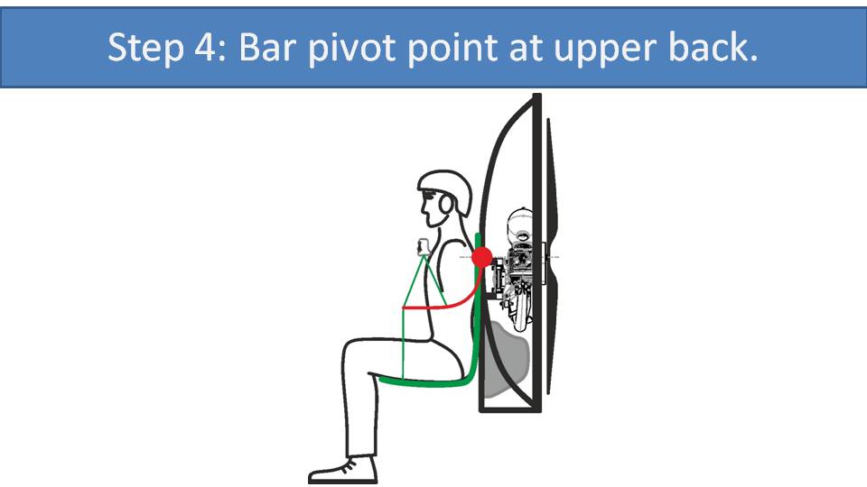
We can just bend the bar upwards, so its pivot point is up at your upper back. This suspension system is now pitch-stable when pushing the speed bar. This is our invention we call the “hybrid bars”, and it’s available with the SCOUT. We call it “hybrid” because it’s somewhere between gooseneck bars and low-suspension bars, and because it combines two materials, the metal bars and the nylon straps.
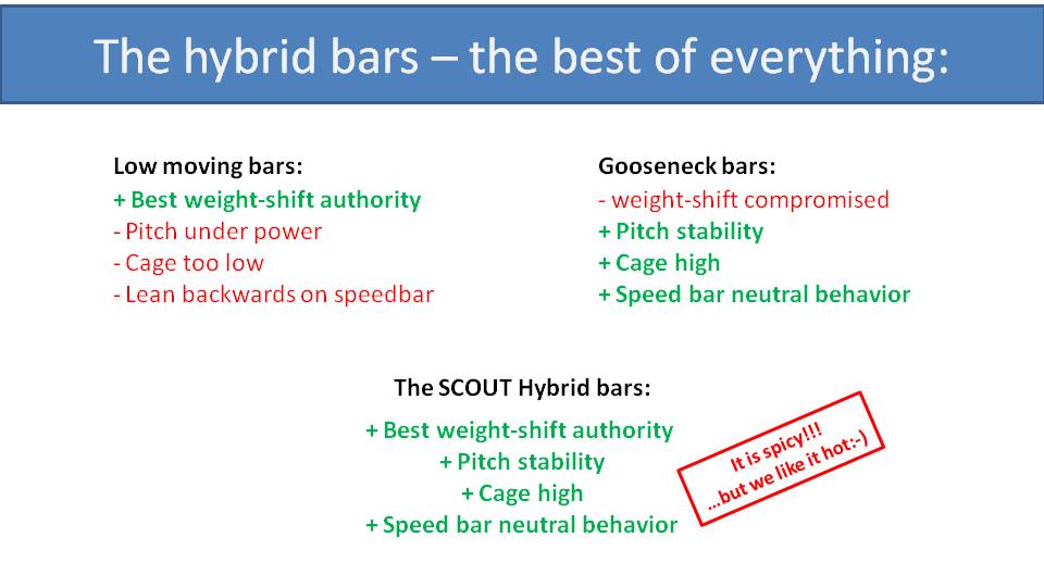
Let’s see how the hybrid bars compare with their rivals. What we love about the low moving bars are their weight-shift authority, but this comes with pitch instability under power, a low cage, and unwanted speed bar behavior. All of this is solved with gooseneck bars, but our weight-shift authority is compromised. The hybrid bars combine the best of the low-suspension and the gooseneck bars. You get amazing weight-shift authority, possibly even better than with low-suspension systems. Flying with the hybrid bars in strong thermal and turbulent conditions can be very twitchy and spicy. So, we primarily recommend them for acro and freestyle pilots who really like it hot.
In the next part, we will be ready to do the big comparison of all the suspension systems, including hybrid bars. We will try to find the best suspension system for cross-country pilots, for freestyle and slalom pilots, for acro pilots, and for thermalling.
I was once asked if high suspension paramotors suck. Absolutely not! Whichever paramotor gets you in the air safely is a great paramotor because you will have the experience of a lifetime. But there are some paramotors that can do it better than others depending on your flying style. –Miro
Part 10: Final Comparison of Suspension Systems
After learning about all the different aspects of paramotor suspension systems, let’s go through the final comparison to determine which best fits your needs.
Here is the lineup of all the suspension systems that we have previously covered. The table is getting quite large and difficult to fit onto one page. Perhaps we could just sum up all the reds, greens, and blues to determine which is the best paramotor design in the world. But that would not necessarily be accurate because each pilot has a different flying style. Different flying styles have different requirements on the paramotor. So, let’s refresh our memory of the flying styles we listed in Part 1:
· Local cross-country flying (probably most pilots)
· Adventure cross-country flying and bivouacking
· Freestyle and slalom
· Acrobatics
· Thermalling with paramotors
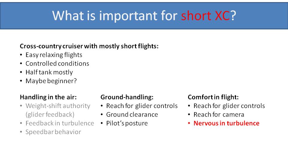
Let’s start with local cross-country flying, which are easy and relaxing flights. They are generally not very long and in controlled environments and conditions. So, weight-shift authority and feedback in turbulence will not be your priority. These flights usually happen without speed bar, so that can be ignored as well. Ground-handling is important, but since you’re not filling the fuel tank to the limit, it won’t be that heavy. So, ground-handling is important, but not the priority. Regarding comfort in flight, it’s good to have a comfortable position for your arms in flight, but as these flights are short, it’s not critical. Regarding how nervous the glider feels in turbulence, it will be advantageous for beginners and many pilots in this group to have a paramotor that behaves calmly in these conditions.
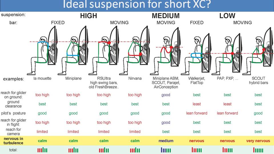
Let’s go back out to the big comparison to see which is the best suspension system for local cross-country pilots. Let’s start with the most important characteristics and then analyze the rest. We have selected low nervousness in turbulence as the most important feature. High and medium-suspension systems are fairly calm and low-suspension systems will act more nervously. In this case we would recommend a high-suspension or medium-suspension paramotor, depending on the pilot’s desire to push their limits.
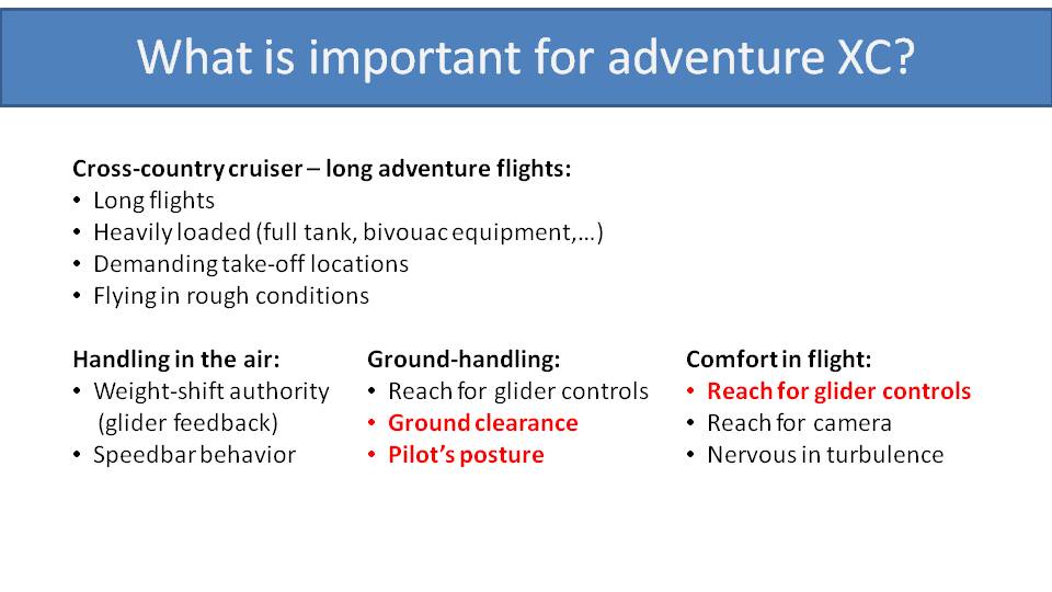
Adventure cross country flying is characterized by long, fully loaded flights. They may include your camping gear and flying all day in turbulent conditions and demanding locations. You probably don’t need much weight-shift authority, but you will need good glider feedback. You will want to know what your glider is doing when you face turbulence, so you can actively pilot it. You also may need to push the speed bar to penetrate headwinds, so its performance is also a consideration. Ground-handling is a crucial characteristic, because when you’re fully loaded with extra gear, cameras, radios, batteries, camping gear, a full tank and maybe even an extra fuel bladder, it is important to have the ability to run as quickly as you can. This is especially true if the LZ is tight or at high altitude. So, ground clearance and pilot’s posture are important when carrying a lot of weight. Your reach for your glider controls is also critical considering the long flight time and you won’t want to go “hands off” in turbulent conditions. Your reach for your camera and gear in flight is important, although not crucial. Regarding the glider’s nervousness in turbulence, it is a part of the adventure to accept it.
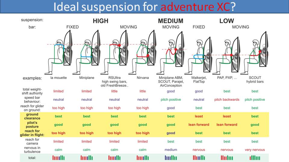
Let’s look at the table now. We have highlighted the crucial characteristics with yellow, and we can see that the medium-suspension system with gooseneck bars is the best combination. With high-suspension systems, you get good ground handling and running, but your arms will get tired. Low-suspension systems will have a much more comfortable arm position but launches will be more demanding.
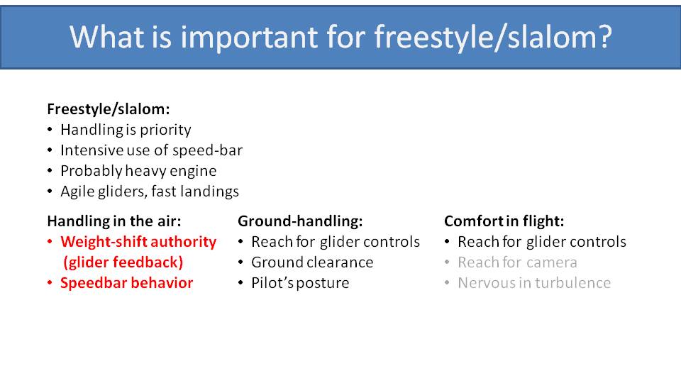
The next flying style is freestyle and slalom flying. Obviously, in-flight handling and control is the top priority. Intensive use of the speed bar makes it a crucial characteristic as well. As a freestyle or slalom pilot, you will likely have a heavy engine on your back and will fly a small, agile, fast glider. This will increase your speed on takeoffs and landings. So, ground clearance and pilot’s posture are important on the ground. Regarding comfort in flight, it’s not a top priority, but something to consider. Reaching for a camera or your jacket zipper is of no importance. As a slalom or freestyle pilot, you probably avoid turbulent conditions, but are skilled enough to handle it.
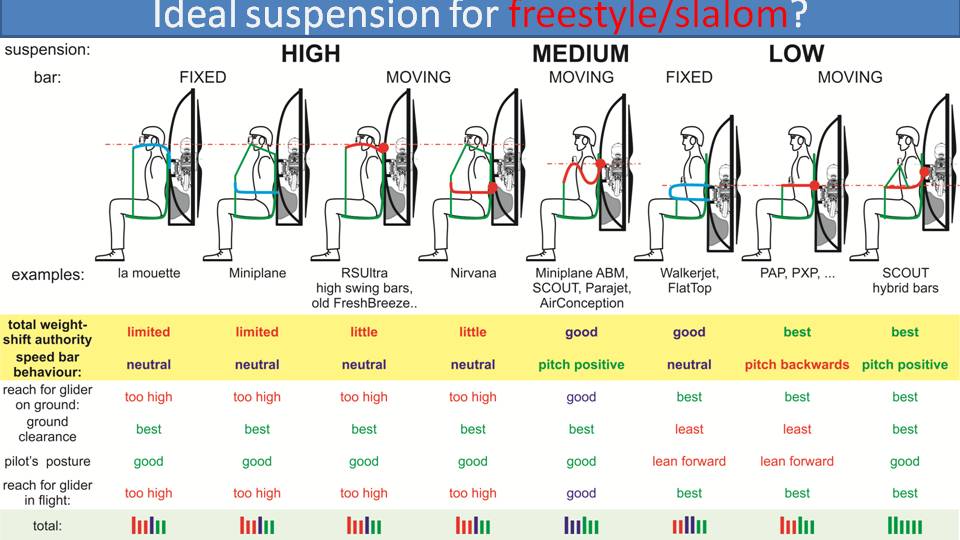
So, the highlighted characteristics are weight-shift authority and speed bar behavior. This rules out high-suspension systems, and you get good results with medium and low suspension systems. The best option is the SCOUT with hybrid bars. You get good results with medium-suspension systems with gooseneck bars and low-suspension systems, depending on which tradeoffs you want to make.
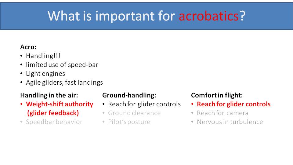
Let’s talk about the ideal paramotor for the acro freaks. It’s all about in-flight handling, which is priority number one. Acro pilots don’t care about speed bar. Ground-handling is not crucial because these pilots normally fly light engines. They are also extremely skilled and can handle any paramotor. Obviously, acrobatics is not about comfort in flight, but a natural position for the arms is advantageous for good acro performance.
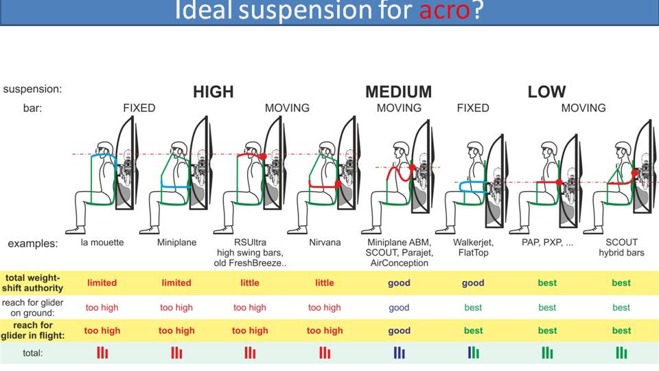
Here is the table with a final comparison and unimportant features deleted. Total weight-shift authority and reach for glider controls are highlighted as the crucial characteristics. Again, high-suspension systems are out of consideration and you get the best performance with low-suspension systems, either with moving or hybrid bars. With some compromises, you get good results with gooseneck bars and fixed low bars.
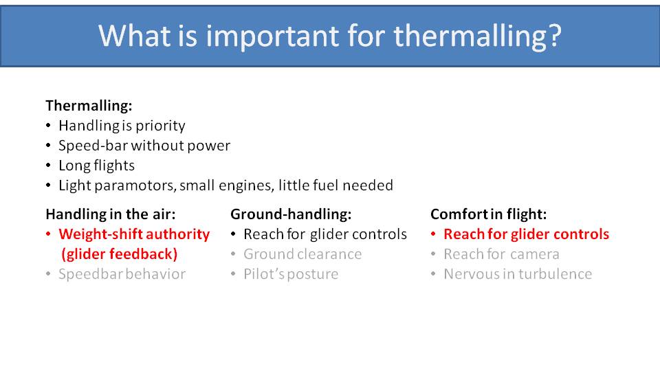
The final, and probably the smallest group of pilots are those who do thermalling. For these pilots, handling and glider feedback are the top priorities. They don’t care much about speed bar as they use the engine mostly for the initial climb-out. Ground handling is not a priority since they don’t carry much fuel and the paramotor won’t be very heavy. They want a comfortable reach for their glider controls, so they don’t have to spend hours with their arms in the air. They also don’t care about a glider that feels nervous in turbulence, since that’s what they seek.
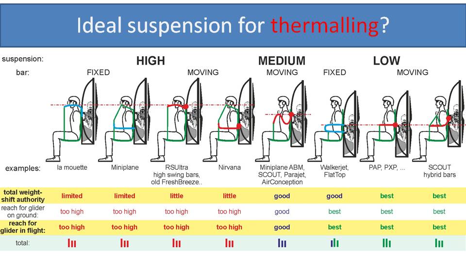
We have highlighted weight-shift authority and reach for glider controls as the crucial characteristics, which removes high-suspension systems from consideration. The best results are with low-suspension systems and very good results with medium-suspension systems.
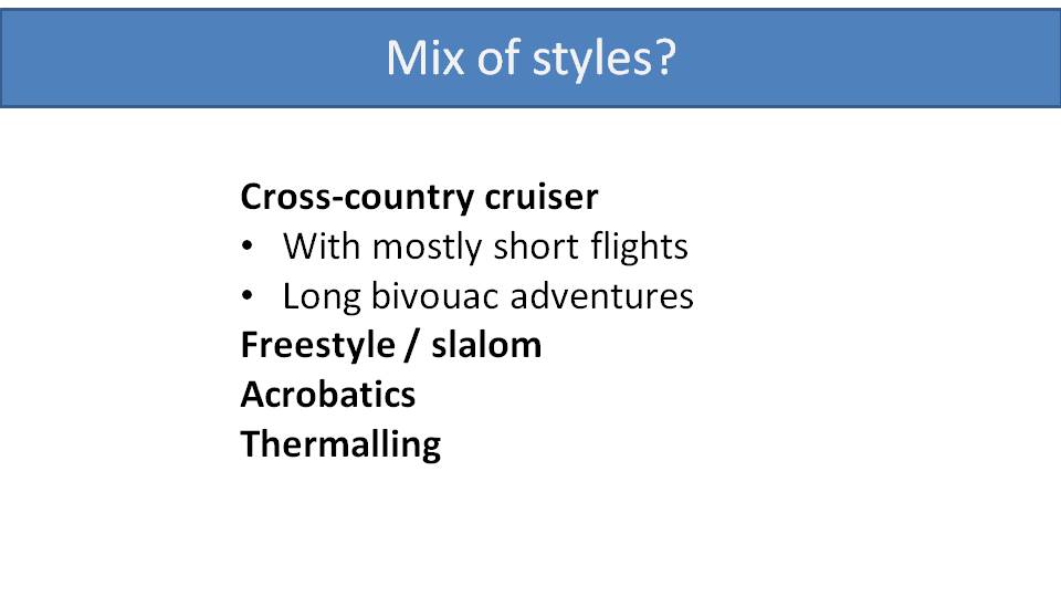
Most of you are not single-style pilots, though. Perhaps you fly short cross-country flights and dream about long adventure flights one day. Perhaps you occasionally throw in some freestyle moves and pull some wingovers. So, when you choose which suspension is best for you, combine the most important aspects of these flying styles to see what suspension system is best. For this mixture, we believe medium-suspension systems with gooseneck bars are the best compromise.
This is the end of the section on paramotor suspension systems. The next section will go into torque a paramotor experiences, the physics behind it, what influences it and how a paramotor’s design compensates for it.
Torque is our enemy. Torque is the reason why paramotors don’t fly straight. There is no way out. Torque affects every paramotor. It’s a law of physics, yet so many pilots have very little understanding of how it works. –Miro
Part 11: Torque
Torque is, by far, the most difficult, complicated, and scientific topic in this series. We will do our best to explain it without using any equations, but we do need to go back to school.
Newton’s third law states that for every action, there will be an equal and opposite reaction.
This is seen with propellers on paramotors. If your propeller spins to the left, it will cause you to spin to the right. How will this affect you in the air?
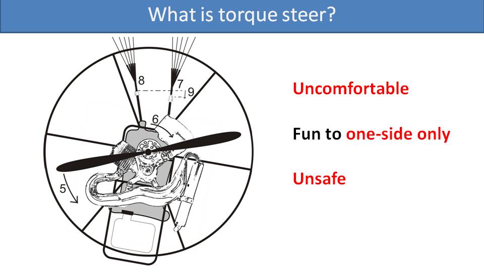
With the propeller spinning to the left, it will cause an opposite reaction on the paramotor. The engine, the frame, and you sitting in the harness, will be rotated to the right. Then, your right riser will be pulled down. This is similar to weight-shift steering and your glider will turn to the right. What does this mean for you? First, it will be uncomfortable because you will need to constantly steer to the left just to keep flight straight. Secondly, it’s only fun to fly in one direction. You would get fantastic turning ability in one direction, but the torque would fight your turns in the other direction. Finally, the torque effect is also unsafe. If the torque steering to the right is too strong, you may end up pulling too much left brake and spin the glider. Also, if your harness is not set up properly, it can cause you to twist into a dangerous situation. We will cover that in detail in an upcoming part.
Every pilot on any paramotor needs to deal with torque and compensate. Yes, there are many misconceptions about torque among pilots.
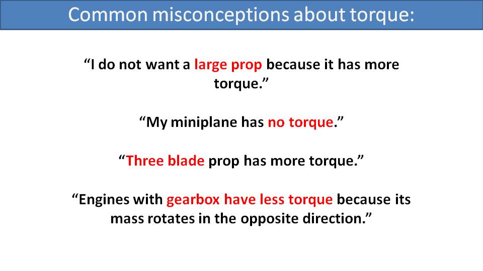
Here are some common misconceptions. Some pilots believe larger propellers impart more torque. We have heard someone say that the Miniplane has no torque. Some believe that 3-blade propellers inherently have more torque. There is even a theory that paramotors with gear drives have less torque than those with belt drives. But these are all myths…let’s bust them.
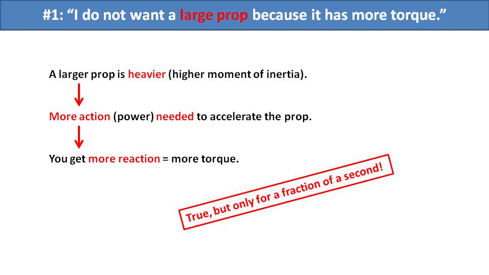
A larger propeller is heavier, which means you need more power to spin it. With more action, you get more reaction. So yes, there is more of a torque effect with a larger propeller, but only for the fraction of a second while spinning it up. Then the story changes once it has reached a constant speed.
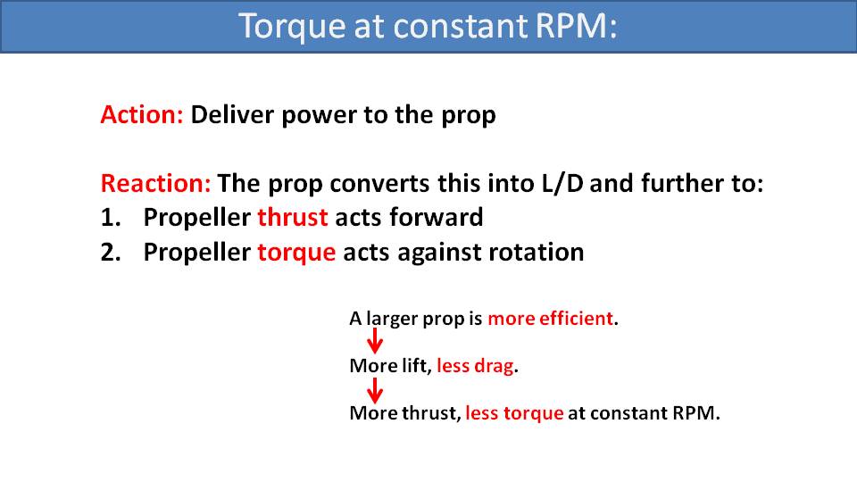
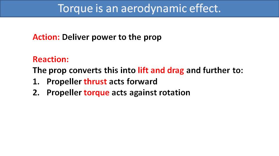
For continuous flight in the air, you hold constant throttle at a constant RPM which delivers power to the propeller. That’s your action. The propeller turns this power into lift and drag, which is a function of its RPM and not its mass. The propeller’s lift is the thrust of the propeller which pushes you forward as its opposite reaction. Its drag is the rotational drag of the propeller through the air, and its opposite reaction is the counter-rotational torque against the paramotor. That’s the “torque effect” that you feel as a pilot.
We will cover this in a future part, but larger propellers are more efficient. This means that for the same amount of lift (thrust), they have less drag. So, larger propellers will have more acceleration torque effect when spinning up, due to their added mass. Then, once you reach a constant RPM to deliver the thrust you desire, they will have less rotational drag and less torque effect than a smaller propeller.
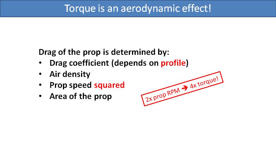
This leads us to an interesting observation. Torque on paramotors during flight at constant RPM is an aerodynamic effect. It is determined by the drag of the propeller as it rotates through the air. Its aerodynamic drag coefficient depends on the propeller’s profile. Some profiles are more efficient than others. Its drag is also affected by the air density, which we can’t really influence. And it’s affected by the propeller’s speed squared and the overall area of the propeller.
The “speed squared” aspect is important. This means that if you double the RPM of the propeller, you get four times as much torque effect.

Let’s see this in a chart using Miro as an example. The propeller’s RPM is on the X-axis and the torque effect is on the Y-axis. With a Vittorazi Moster Plus, his glider, and his weight, he needs about 5000 RPM at the engine for level flight. With the 2.72 belt drive reduction, this is reduced to 1800 RPM for the propeller. For level flight, at 1800 RPM, the torque effect is right there at the edge of the green range. If he goes to full throttle, the 8600 RPM of the engine translates to 3100 RPM for the propeller. So, for 72% more RPM he will experience 3 times as much torque effect, using the squared function. That’s an immense increase of torque experienced between level flight and full power climb out.
Now, why did we color the bottom half green and the top half red? Most paramotor manufacturers design them such that they balance the torque effect for level flight. This means that while cruising at that constant RPM, you won’t feel any torque, and we’ve colored that area and below in green. But the red area above indicates the immense increase in torque you will need to deal with as you increase the throttle for a full power climb.
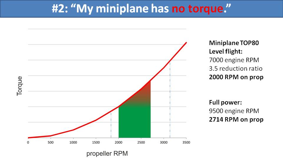
The story changes when we put Miro on a smaller engine, which leads us to the second misconception we heard: the Miniplane has no torque. With the small Top 80 engine on the Miniplane, Miro would need about 7000 RPM to maintain level flight. That engine’s 3.5 ratio gear reduction converts to 2000 RPM on the propeller, which is smaller than in the Moster Plus example. Full power on this engine is 9500 RPM which is 2700 RPM at the propeller. This is only a 35% increase between cruising RPM and max RPM. Doing the math, this only leads to an 84% increase in torque for max throttle versus the 300% increase for the Moster Plus. But then the climb rate on the Top 80 is much less. If the Top 80 could magically spin up to 12000 RPM to achieve the same top-end thrust as the Moster Plus, then it would also have that same 300% increase in torque effect. So, the torque is still there, it’s just physics. But, with a limited power range, you have limited torque effect as well. Small engines still have torque, but they’re limited.
Let’s move to the third misconception, that three-blade propellers have more torque. They have more mass than 2-blade propellers, so there will be more torque during acceleration. But they can be slightly more efficient than two-blade propellers at the same profile and length, so the torque effect would be slightly less.
The fourth misconception is that paramotors with gear reduction drives have less torque than those with belt reduction drives. The reasoning is that the crankshaft and the gears rotate in the opposite direction of the propeller. Recall that we explained that the torque effect during constant-RPM flight is an aerodynamic effect. The crankshaft and gears experience virtually no aerodynamic drag tucked away in their housings. The only help that the counter-rotating mass of the engine can do is while accelerating the propeller, but even then, it’s a small mass at a small diameter compared to the propeller. So, the benefit is unnoticeable.
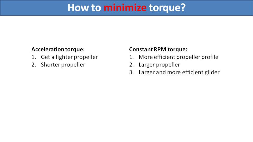
Now that we know how the torque effect works, let’s analyze how we can minimize it. For acceleration torque, you can use a lighter or shorter propeller. But acceleration torque is of no importance to a paramotor pilot. You can feel it when revving your engine on the ground, but it doesn’t affect your safety, your control, or your fun in the air. What’s more important is to minimize the aerodynamic torque of the propeller observable in constant RPM flight. For this, you can choose a more efficient propeller profile. Carbon fiber propellers usually have more efficient and thinner profiles than wooden propellers. You can choose a longer propeller. A larger and more efficient glider would decrease the RPM necessary for cruising, thereby reducing the torque effect. But these choices do not eliminate the torque effect by any means. It is still there. This means we need to compensate for it, which we will discuss in the next part.
My professor of mathematics would sometimes point to a solution and say, “this is a great solution, but useless.” This is pretty much the same with counter-rotating propellers on paramotors. Let’s explain why. –Miro
Part 12: Counter-Rotating Propellers
Let’s start with why counter-rotating propellers are so great. In fact, they are the ideal solution to fight the torque effect. With two equal propellers spinning in opposite directions, the torque effect from each is perfectly compensating for the other. They each work with the same laws of physics and are the only solution that can perfectly compensate for both acceleration torque and aerodynamic torque during constant-RPM flight.
But there are some serious disadvantages.
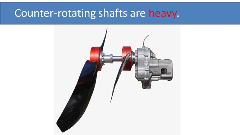
First, the mechanisms required for counter-rotating shafts are heavy, which is obviously a big disadvantage for paramotors.
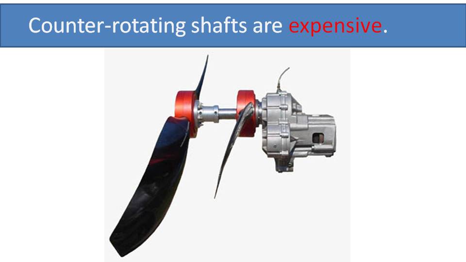
Secondly, it’s an expensive, complicated system which is another thing that can fail in the air.
You will also immediately notice the slow throttle response. With twice as much propeller on your back, you will need twice as much power to accelerate it. Since you don’t have twice as much power, it will take twice as long to reach your desired RPM.
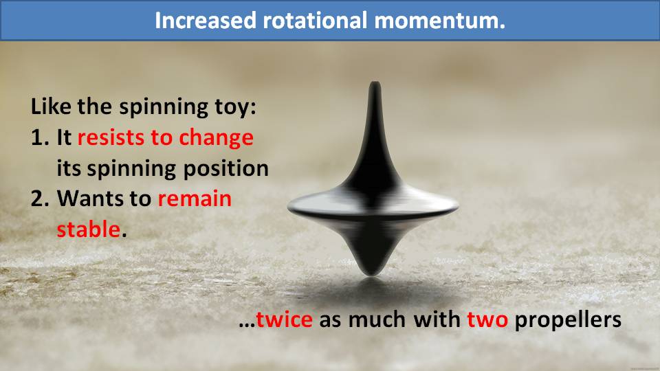
Spinning propellers, like any other spinning objects, want to remain stable. They will resist changing their position in space, like the spinning tops you used to play with, due to the gyroscopic effect. You can feel this in the air when you initiate a turn. For just a moment, the paramotor hesitates to follow the turn and wants to continue in the same direction. This effect would be more dramatic with a counter-rotating propeller system since the rotating mass is more than doubled. It would definitely affect your handling.
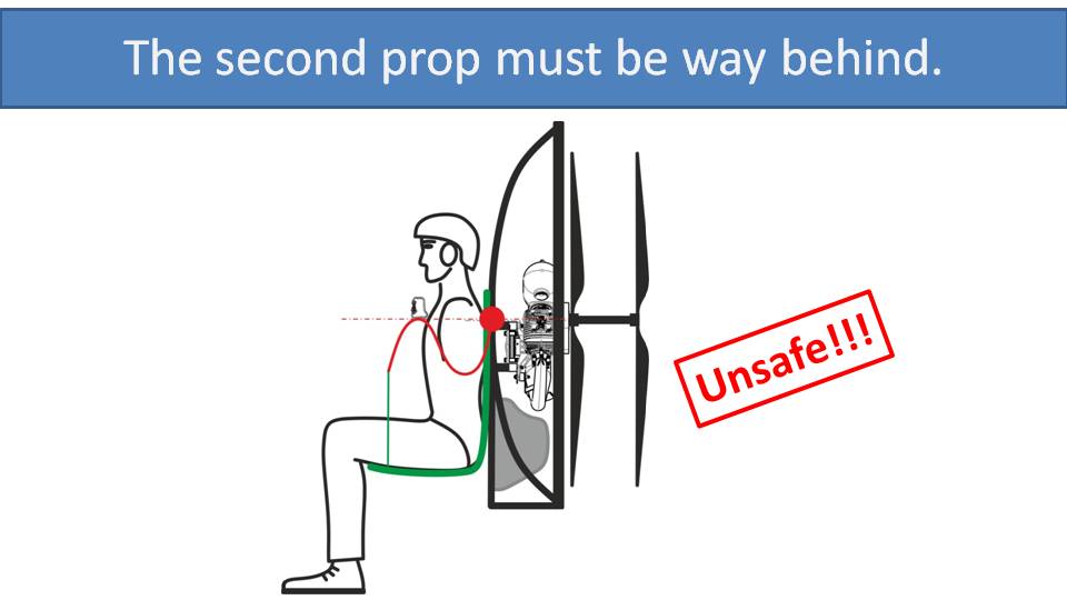
Finally, are the serious safety concerns with counter-rotating propellers. The second propeller would need to be positioned far behind the first propeller to avoid interference. This would greatly increase the risk of cutting lines or hitting something else while on the ground.
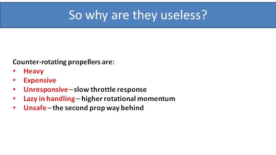
While counter-rotating propellers are the ideal way to compensate for torque, they are heavy, expensive, unresponsive when handling, and unsafe. Therefore, we don’t see them on typical gasoline paramotors.
We are big fans of innovation. So, if anyone has ideas that can fix these disadvantages of counter-rotating propellers, let us know! This would make for the best paramotor ever. For example, there are some experimental electric paramotor designs that use four motors, each with a small propeller. Two motors rotate in the opposite direction from the others to perfectly compensate for torque. But the small propellers are much less efficient and quickly drain the batteries. So, until we have a better solution, we will need to use other means of compensating for the torque effect. We will talk about this in the next few parts.
My first paramotor had a high-suspension system. I want to tell the story of how I almost ended up in a vineyard while landing it because I didn’t pay enough attention to its torque compensation. –Miro
Part 13: Torque Compensation on High-Suspension Paramotors
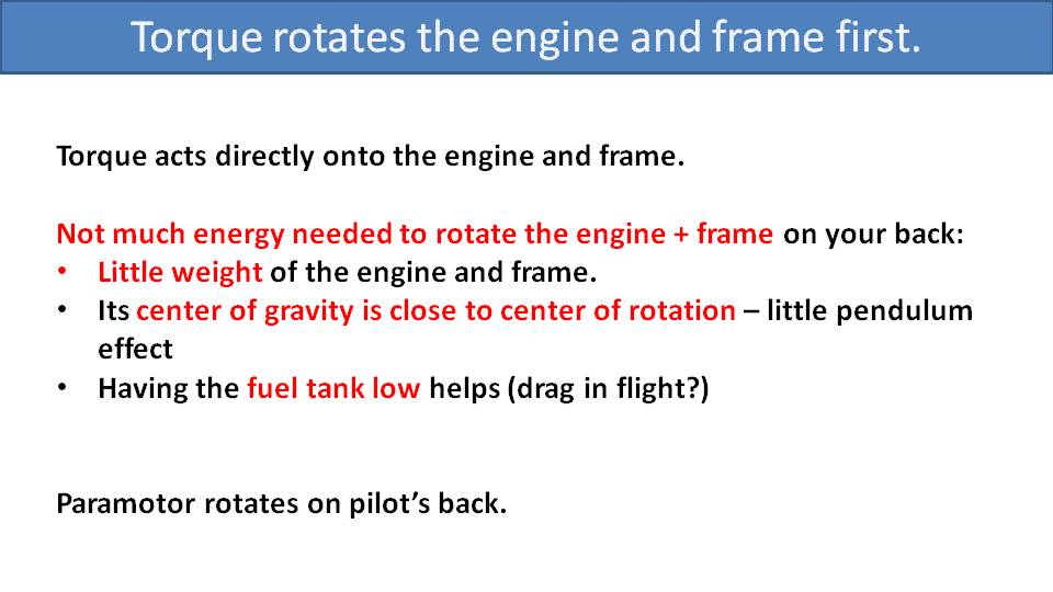
Torque is a surprisingly powerful force that turns the engine and frame on your back in the opposite direction of the propeller’s rotation. It’s easy to rotate the engine and the frame on your back because the engine and frame have relatively low weight and their center of gravity is close to the center of rotation. The easiest way to observe this is by watching a paramotor pilot taking off from behind. While they’re still on the ground running under full throttle, they are not yet sitting in the harness or suspended by the glider. So, the pilot’s weight and the frame geometry offsets cannot counteract the torque and you can see the frame rotate on the pilot’s back. This is awkward and suboptimal behavior.
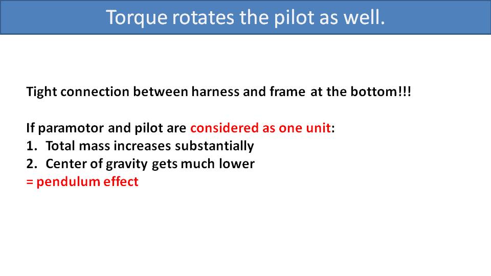
The way to prevent this is to ensure a tight connection between the harness and the frame so they cannot move relative to each other. To do that, you need to connect the frame to the harness at the bottom. This is an easy solution that many manufacturers fail to do.
Once the pilot, the harness, and the engine are connected as one unit, it’s a different story. The torque of the propeller is not just rotating the 25kg mass of the paramotor. It now needs to rotate perhaps the 120 or 130 kg of the pilot and the paramotor together.
Then, once the pilot is sitting in the harness, there is a lot more mass suspended from the glider, the center of gravity gets lower, and you get the pendulum effect.
Visualize a paramotor with a high-suspension system suspended at the glider as a pendulum. If we apply power and torque at the paramotor, it will rotate the pendulum sideways. At a certain distance, the weight of the pendulum will stop the rotation and the paramotor will maintain that angle of rotation within the pendulum with that power applied.
But you are still facing torque, and you should still be weight-shifting to compensate for that torque. But there is a solution for this for high-suspension systems, and that is a diagonal strap. It’s a simple solution and it works well.
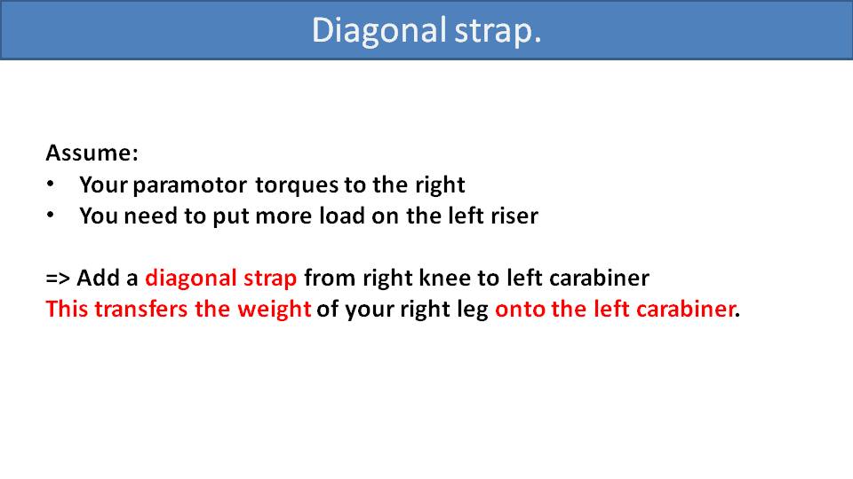
Let’s assume that the paramotor is torquing to the right. In this case, the diagonal strap would go from your right knee in your harness up to the left carabiner. This transfers the weight of your right leg to the left carabiner, effectively weight-shifting to the left. This strap is adjustable, so you can alter the amount of weight transfer to the left based on how much torque you are experiencing.

Let’s use Miro as an example at level flight. He would need 5000 RPM on the engine which translates to 1800 RPM of the propeller. The blue line would be the torque he faces at level flight. So, he can adjust his diagonal strap to perfectly compensate for that amount of torque at level flight. The paramotor would be perfectly balanced with no tendency to turn left or right. However, if he goes to full power for a strong climb, his torque increases rapidly. But the diagonal strap isn’t changing to compensate. So, at full power, he is facing the additional torque above the blue line.
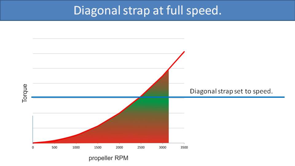
But as we said, the diagonal strap is adjustable. So, if he were to do an extended full-power climb or change the trimmer settings, he can adjust the diagonal strap to compensate and stay well balanced again. The obvious issue is that the adjustment is not quick. So, if you’re making aggressive throttle changes for some extra fun freestyle flying, you cannot quickly adjust the strap.
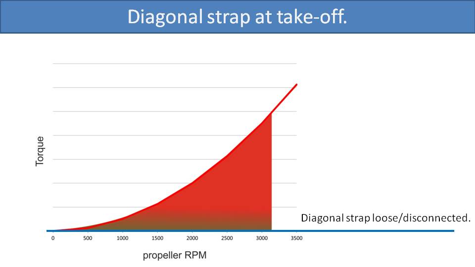
Barring this, it’s all sounding good for torque compensation. But it gets more complicated on takeoff. While standing upright on the ground, the distance between the left carabiner and your right knee is much longer than when sitting. So, to run, you need to have this diagonal strap very loose or disconnected altogether. This means for a full-power climb after launching, the strap will not be providing any torque compensation. You must be incredibly careful to weight-shift and steer the opposite direction while being gentle with the throttle to avoid dangerous riser twist.

Similarly, you must release the diagonal strap when landing. Thankfully, you should be off throttle while landing, so you will be in a neutral state with no torque shift.
This is what happened to me once while I was paramotoring on a high-suspension unit. I was approaching my tight landing spot with the diagonal strap perfectly set for my level flight. I had a very balanced flight, but I forgot to disconnect the diagonal strap for landing. Before landing, I did two things: I released the throttle and I got out of the harness. By releasing the throttle, the torque went to zero because the prop had no power. Secondly, by getting out of the harness, I applied a lot more tension to the diagonal strap. This is because I straightened my body, which made my right leg pull the left riser down, effectively weight-shifting even more to the left. So, I had zero torque to the right and a lot of weight-shift to the left, and I almost crashed into a vineyard. Luckily, I was uninjured and just damaged my glider. I learned from this lesson. Please do the same and never forget to disconnect your diagonal strap prior to landing. –Miro
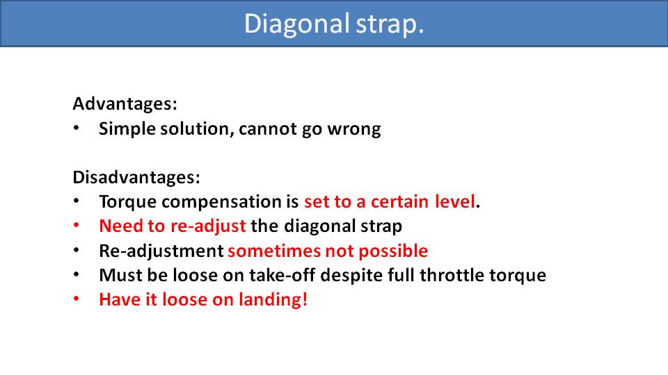
To summarize, torque compensation on high-suspension paramotors is done with a diagonal strap. It’s a wonderful, simple solution that can perfectly compensate for torque. But there are some disadvantages. The torque compensation is set to a certain level that you need to readjust every time you change your flight speed. Readjustment is not possible when you’re making quick throttle changes, like for freestyle flying. The diagonal strap must be loose for takeoff, which means you will face full uncompensated torque on takeoff. And please don’t forget to disconnect or loosen your strap before landing, or you will end up in a vineyard.
Traditional offset torque compensation for medium- and low-suspension paramotors is simple and easy. It doesn’t give us ideal results, but it’s the second best we have. –Miro
Part 14: Torque Compensation on Medium- and Low-Suspension Systems

For medium- and low-suspension systems, there are two typical ways to compensate for torque. The first is the pendulum effect, which is inherent with paramotors, and the second is by designing in a suspension bar offset.
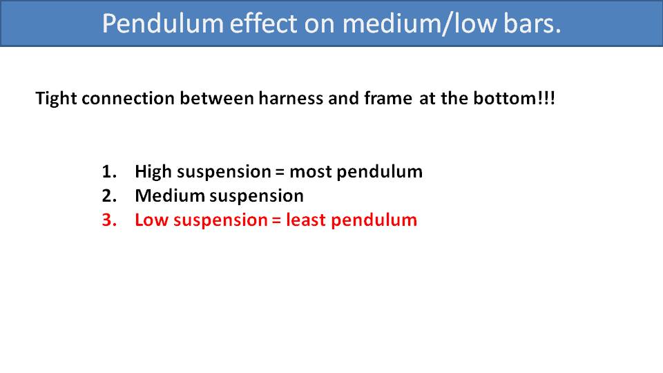
The pendulum auto-balance effect was explained in the previous part. But it works best with high-suspension systems since the pilot’s center of gravity is furthest from the glider. Imagine a paramotor as a pendulum suspended from the glider. The further away the paramotor is from the glider, the stronger the effect of the pendulum is to bring the paramotor back into balance. So, low-suspension systems will have the least auto-balance effect, and medium-suspension systems will be somewhere in the middle.
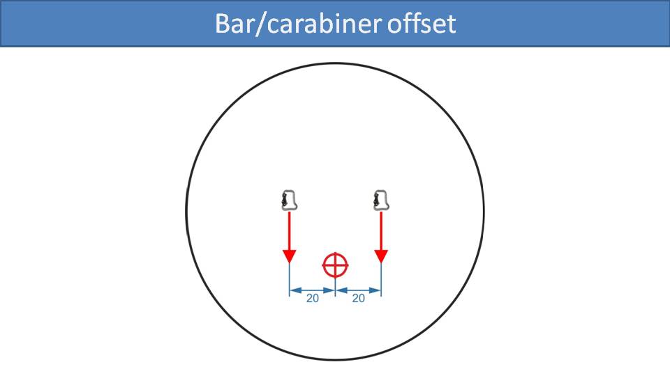
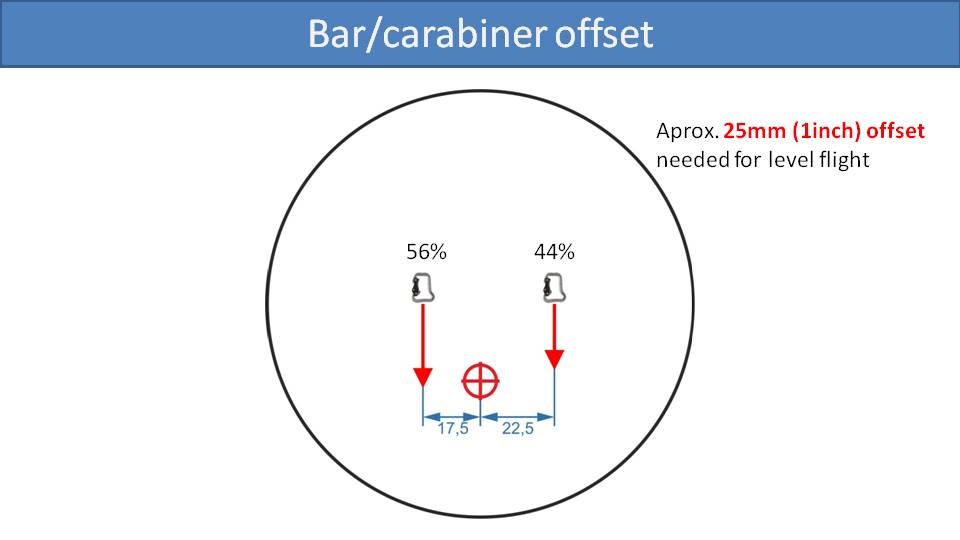
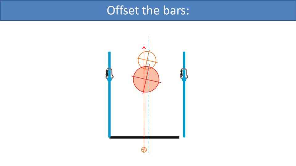
To analyze bar offsets for torque compensation, let’s start with symmetric carabiners in respect to the paramotor’s center of gravity. If the distance between the carabiners and the center of gravity is equal, then the load will be evenly distributed to both carabiners.
If your paramotor is torque steering to the right, then you need to put a bit more load on the left side to compensate. To do that, you shift your carabiners to the right.

Here, the left carabiner is closer to the center of gravity and the right carabiner is further away. Because your center of gravity is closer to the left carabiner, a larger portion of your weight is loaded onto the left carabiner, effectively weight-shifting to the left. Based on our experience and observations, a 25mm offset is needed for an average pilot on an average engine to compensate for torque at level flight.
This is a good indication of just how powerful the torque effect is. Because with that offset, a typical pilot would load the left side about 15kg more than the right side to compensate for that torque at level flight.
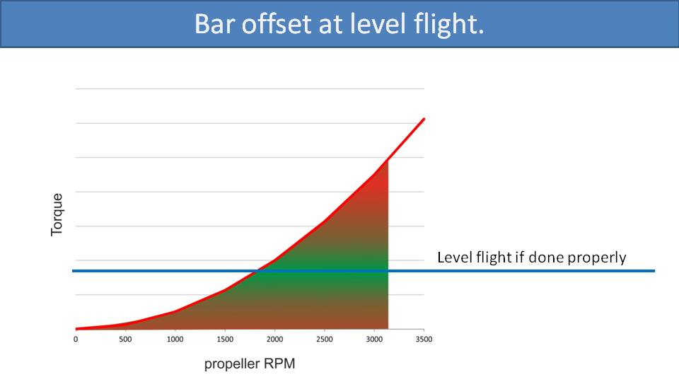
Here is our torque chart from the previous parts. The RPM is on the X axis and the torque, which is a square function of the RPM, is on the Y axis. Let’s say we need 1800 RPM at the propeller to maintain level flight. If the paramotor is designed properly and has the appropriate amount of carabiner offset, then we will get the necessary amount of torque compensation for level flight. So, at level flight, the paramotor will be right in the middle of the green band and perfectly balanced.
If the offset is less than 25mm to one side, then the torque compensation will not be sufficient. In effect, the green band on the graph will shift down. Then, with the RPM indicated by the blue line to achieve level flight, you are now edging towards the red zone and your paramotor won’t be balanced.
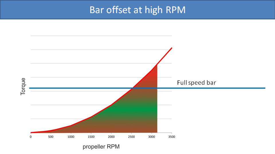
Let’s look at what happens when you push the speed bar and add throttle to maintain level flight. With the increased RPM, you will end up flying in the red zone. The torque compensation from the bar offsets will probably not be sufficient and you will not be balanced. So, at full speed bar, you need to compensate for torque steering with weight-shift, braking, or tip-steering in the opposite direction.
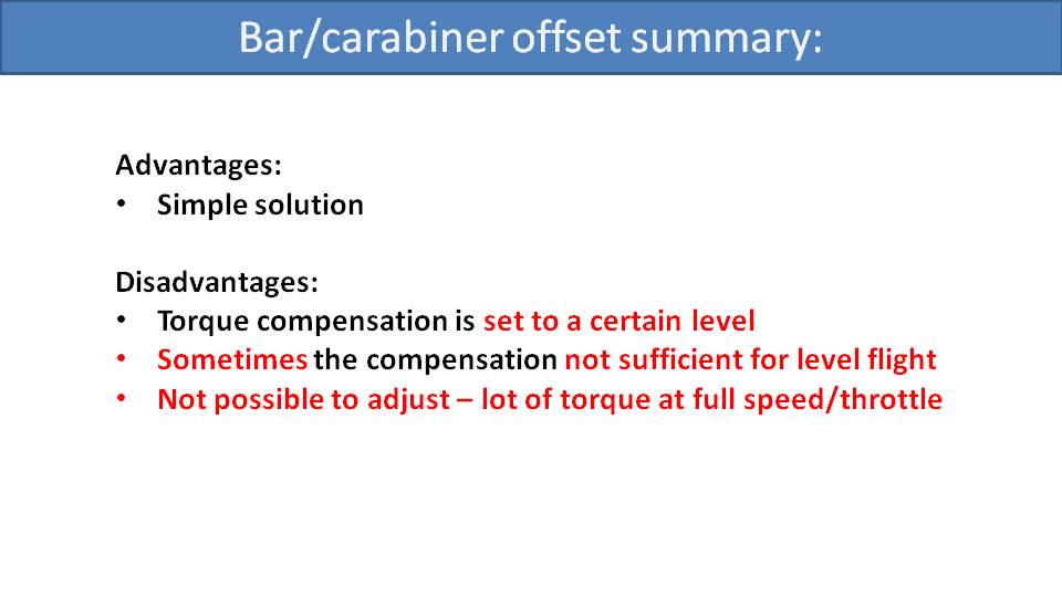
Here is our final summary for bar and carabiner offsets for medium- and low-suspension systems. The advantage is that it’s a simple solution with no maintenance or in-flight adjustments that the pilot needs to worry about. For disadvantages, the torque compensation is set to a specific level in its design. Sometimes, that torque compensation is not correct for level flight, which can be annoying. Also, torque compensation using bar offsets is not adjustable. So, if you need more compensation for climbing or full speed bar flight, you must do that on your own.
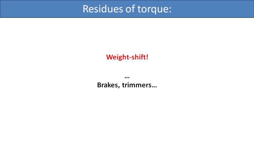
With the medium- and low-suspension systems, you may find yourself dealing with residual torque left uncompensated. The best way to fight it is with weight-shift. Luckily, medium- and low-suspension systems have good weight-shift authority, and it is the recommended technique. You can also pull some opposite brake or tip steering. Doing that for long stretches is annoying and uncomfortable. So, some pilots will adjust one trimmer to be lower than the other. For example, if your paramotor is torque steering to the right, then you can pull your left trimmer in a little. That will steer you back to the left to compensate. We discourage this technique because, in case of a collapse, recovery may be affected. The geometry of the glider will not be symmetric, and the recovery behavior could be erratic and unpredictable.
The last method of compensating for torque is the SCOUT Dynamic Torque Compensation which we will explain in the next part.
There are different ways to offset the suspension bars for torque compensation, but one method is much better than the others. –Miro
Part 14.2: The Best Type of Bar Offset
Let’s go into detail about the different types of suspension bar offsets to compensate for torque.
Here we recall the diagram from part 14 that explained how a bar offset works for torque compensation.
This is a picture of a Miniplane. We believe they were the first to introduce gooseneck bars into this sport and deserve respect for this fantastic innovation. Gooseneck bars eventually became an industry standard and most major paramotor manufacturers use them now. Many years ago, Miniplane made these gooseneck bars from a simple bent metal tube construction. However, they bent the tubes skewed a bit to the side. It’s a strange shape, but it makes perfect sense once you examine the physics behind it.
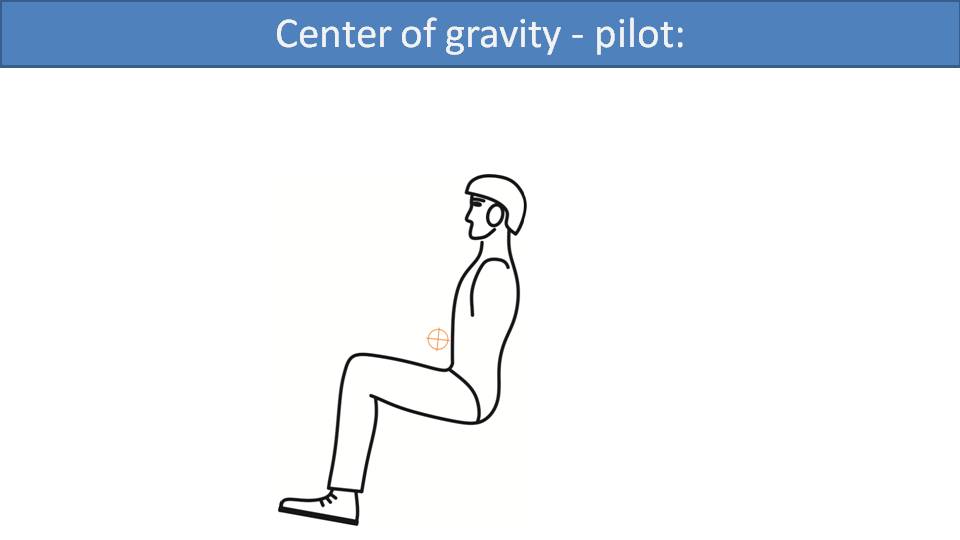
Let’s start by looking at the weight distribution of the pilot, the paramotor, and then combine them. Here is a seated pilot whose center of gravity is above their lap a bit at the mark in the picture, perhaps a bit higher.

The center of gravity of the paramotor is roughly at the red mark near the engine mounts. We made its mark much smaller than the pilot’s center of gravity mark because the paramotor is much lighter than the pilot.
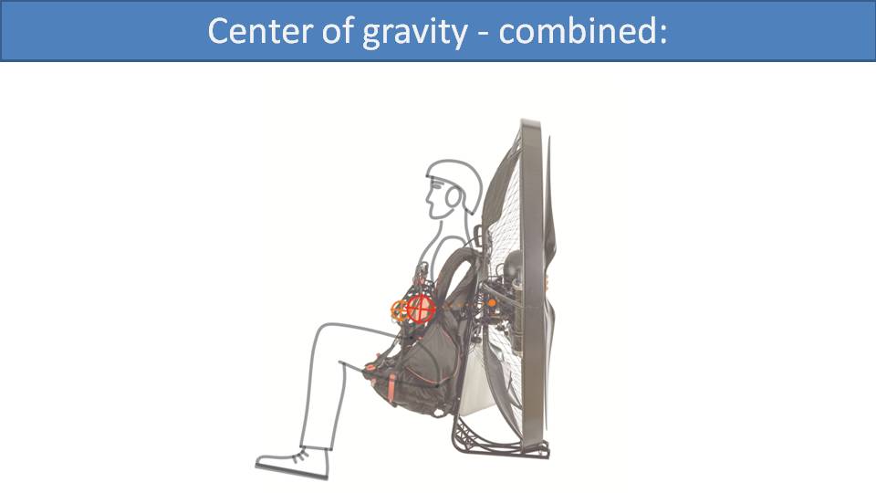
When we combine the two, the new center of gravity will be on the line between the center of gravity of the pilot and the paramotor. Because the pilot is much heavier, the combined center of gravity will be closer to the pilot’s center of gravity, up near the front of the gooseneck bar. So, most of the weight is loading the front of the gooseneck bar and a smaller portion of weight is loading the back of the gooseneck bar where it’s attached to the frame. All the weight of the engine is hanging on the back side of the gooseneck bar by its pivot point.
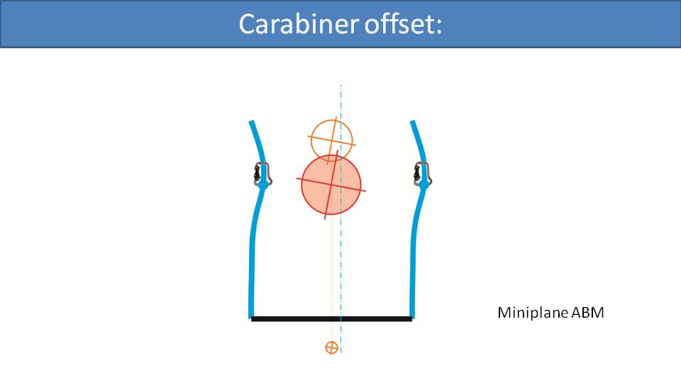
Let’s look at the Miniplane suspension bar geometry from above. The black line at the bottom is the paramotor frame. The marks in the center, from top to bottom, are centers of gravity for the pilot, the pilot and the paramotor combined, and the paramotor alone. The blue lines are the gooseneck bars that are skewed to the right. Their center line, the dashed line, is offset to the right of the combined center of gravity. Because the left carabiner is closer to the center of gravity, it will be more heavily loaded. This will compensate for the torque effect, assuming that torque steer is to the right. This is a great simple design that we discussed in the previous part. It’s so clever, that it’s the most copied design for gooseneck bar offsets for torque compensation.
Some designs CNC machine straight gooseneck bars and then bolt on an offset onto one side of each of the bars to shift the carabiners, which accomplishes the same effect. There is a “but”, however. Every solution usually has its disadvantages.
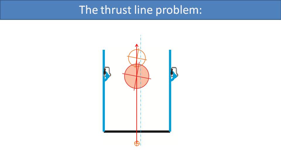
The main problem here is the thrust line. The red line indicates the thrust line, and the blue line indicates the center line of the carabiners. So, just as the carabiners are offset to the center of gravity, which is what we want, they are also offset to the thrust line. This means that more thrust will be transferred to the left carabiner than the right one. If this difference is moderate, it’s not a big issue. But, if the offsets are larger, then it will lead to twisting tendencies under full power. This is the reason why some paramotors with bar offsets are not perfectly balanced for torque. In theory, they would require a larger offset to compensate for torque, but the offset from the thrust line becomes too dangerous.
This was not an issue with the Miniplane, because it had a small engine. But, if you applied this same geometry with a Moster Plus, which has twice as much power, then you cannot offset the carabiners enough to compensate for all that torque. That would expose the pilot to those twisting tendencies under full power. So, with this offset system, there must be a compromise. You compensate with the bar offset, but not all the way. It’s a simple system that’s effective and looks good, but it’s not perfect.
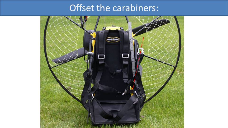
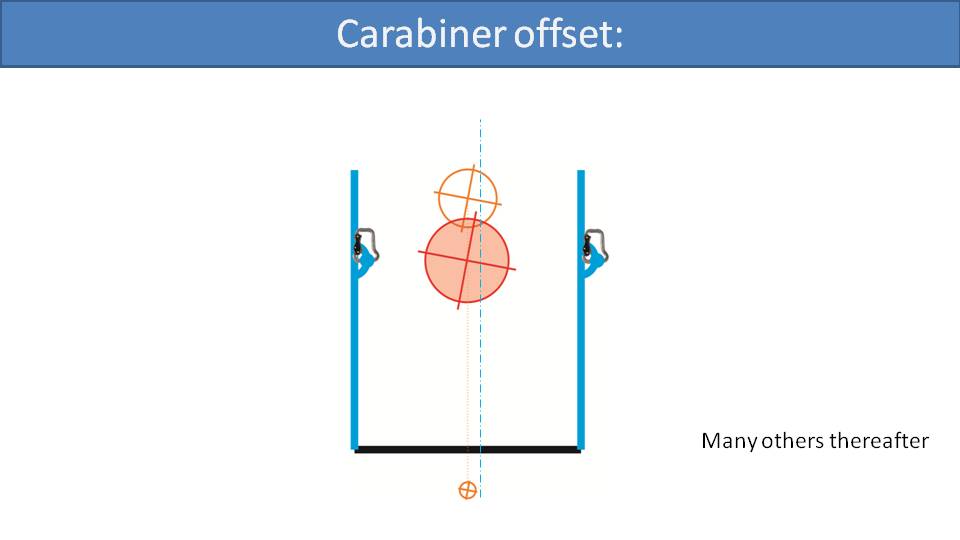
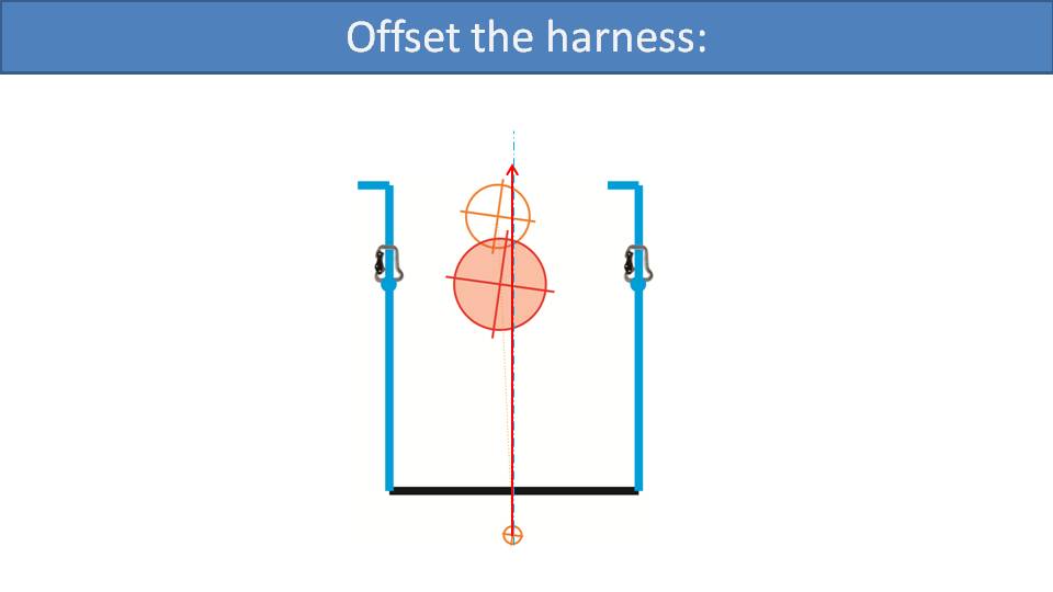
Let’s discuss another solution. There are some paramotors, but not many, that move one bar to the side. This is done by adding a spacer, up to 5cm, in between the bar and the frame. In this example, this is done on the right bar. It moves the carabiner (on the bar) to the right, just as in the previous example, but unfortunately it moves the pilot as well. This is because it also moves the front of the bar, where the harness is attached, to the right as well. Most of the pilot’s weight is suspended from that point. So, while moving the right carabiner away from the center of gravity, the pilot’s weight follows along to a degree. We can see that the dashed blue line, the center line of the carabiners, moves to the right to provide weight-shift compensation to the left. But, the combined center of gravity also moves a bit to the right and reduces the weight-shift. So, this torque compensation is far less efficient than just moving the carabiners alone.
There is another solution that is our favorite, but surprisingly it is not used much. In this design, the bars stay in a neutral position, symmetric with the thrust line. Then, you add an offset to the front of the bars, where the harness is attached. So, instead of moving the carabiners to the right, you move just the pilot to the left. The carabiners stay perfectly centered with the thrust line. So, thrust is applied evenly to both risers and there will be no twisting tendencies, even under full power. The rear of the harness can also be mounted to the side to make it more effective. With this design, all the pilot’s weight is shifted toward the left carabiner, imparting a small weight-shift turn to the left that compensates for the torque steer to the right. Not many paramotors use this design, but one example is Fly Products. Let’s have a look.
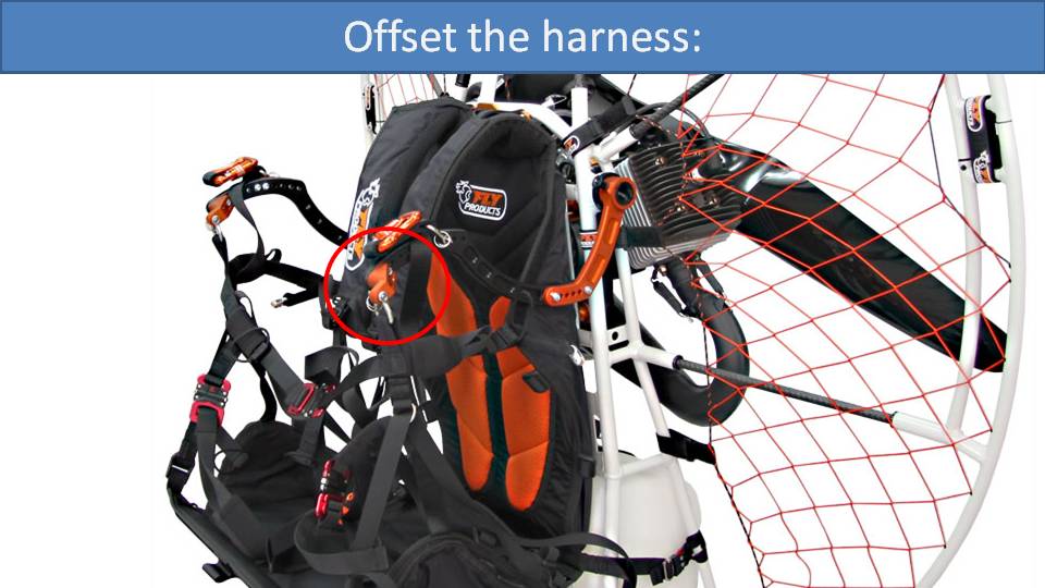
This is a Fly Products paramotor. The gooseneck bar is straight and symmetric with the thrust line. At the tips of the gooseneck bars are machined offsets that move the harness suspension points to the left. This is the best method for offsetting the carabiners for torque compensation.
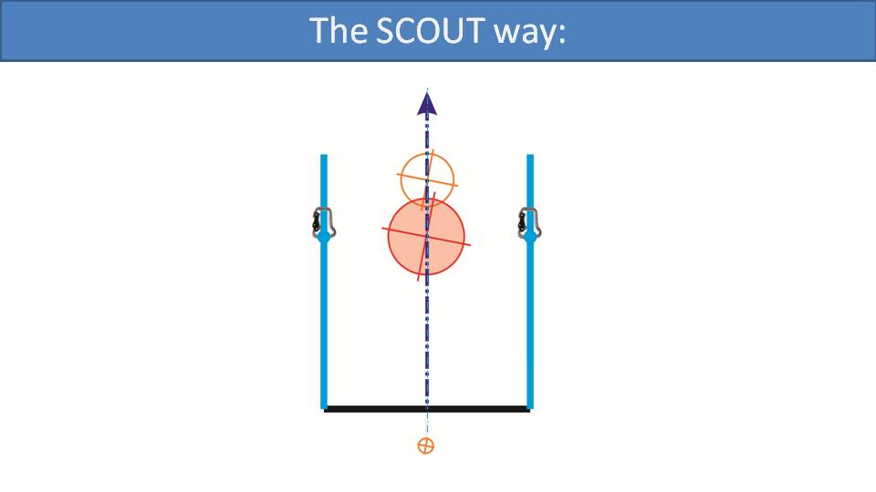
Although we stated the harness offset technique was our favorite method for offset torque compensation, it’s not the best method for torque compensation in general, and not what we did on the SCOUT. On the SCOUT, the bars are completely symmetric around the pilot and the thrust line. There is no offset and no compensation with the suspension bars because we compensate for the torque effect in a completely different and innovative way. Our technique is called SCOUT Dynamic Torque Compensation and is our patented technology. We will explain it and go into detail about it in the next part.
Let’s talk about the simplest and best way to compensate for torque. But it’s the most difficult to explain. Again, I promise no equations. –Miro
Part 15: SCOUT Dynamic Torque Compensation
SCOUT Dynamic Torque Compensation was invented by our chief designer, Miroslav Svec, and we’d like to share its story.
Let’s share a slide from part 11 where we conclude that the torque we face in paramotors is an aerodynamic effect. Recalling Newton’s third law about action and reaction, the propeller gives us two actions. It has lift and drag, which are converted into thrust and torque.

The torque effect is correlated to the square of the propeller’s speed, which gives us a rapidly increasing amount of torque effect as more power is applied. Other methods of torque compensations discussed in previous parts are static. They can only compensate for torque a specific power level. At any other power level, be it full power or at idle, they will either be over-compensating or under-compensating. Miro’s idea was, since torque is an aerodynamic effect, let’s compensate for it with another aerodynamic effect.
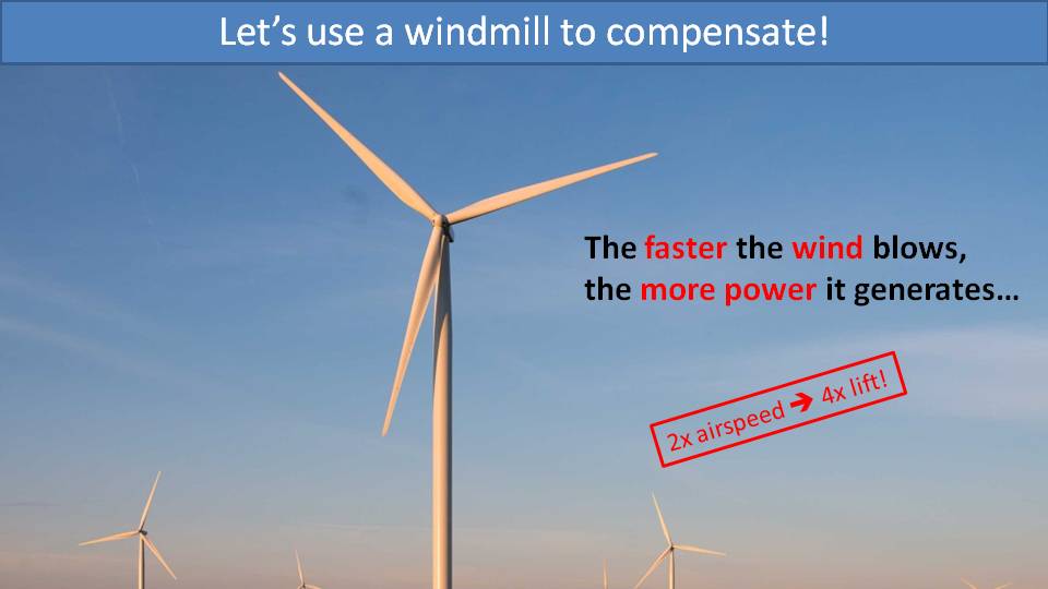
There is a simple concept that you’re all familiar with, which is the windmill. The faster the wind blows, the more lift the windmill generates. The windmill converts this lift into torque against the generator inside which creates electricity. So, if we build the paramotor cage in the shape of the windmill, we could use the windmill’s torque to compensate for the propeller’s torque instead.
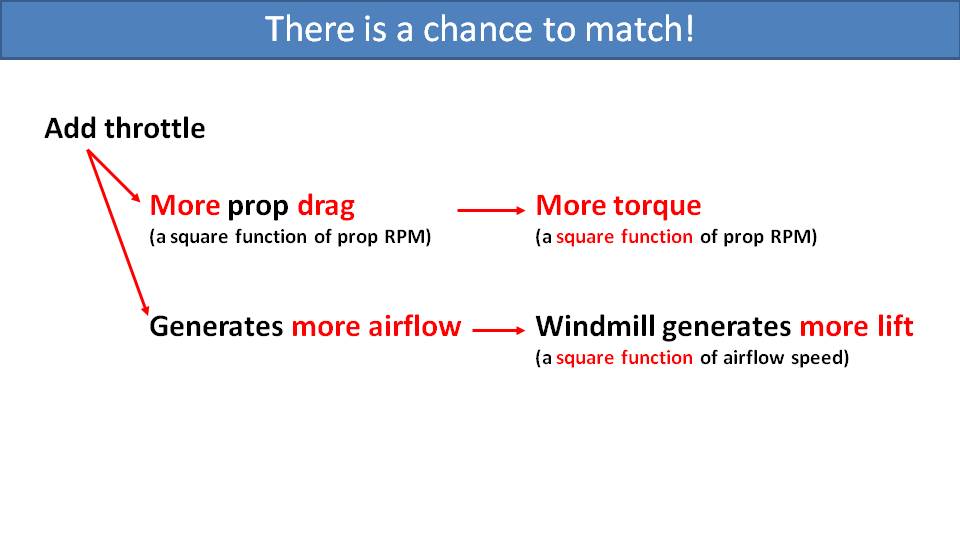
Let’s see how this would work. If you add power and increase the speed of the propeller, it will have increased drag which will lead to increased torque effect. At the same time, the propeller generates a lot more thrust. This increased thrust is now increased airflow through the windmill built into the cage. The windmill generates more lift which is converted into more compensating torque in the opposite direction. The cool thing about this is that both the propeller’s torque effect and the torque compensation of the windmill are aerodynamic effects. They are both related to the same principles of aerodynamic physics, which are squared functions of the propeller’s RPM and the airflow speed.

Miro’s goal was to build a windmill into the cage and design its size and profile in such a way that its compensating torque, the blue line, will increase at the same rate as the increase in the propeller’s torque, the red line.
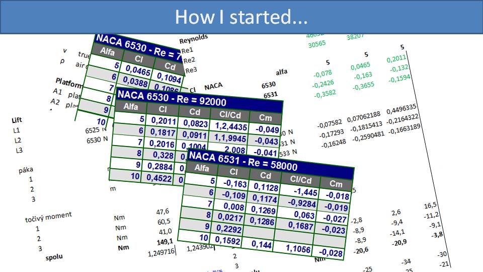
Miro started with measuring the actual torque at various RPMs of the engine. This was a fun experiment and amusing to see. He suspended his paramotor from a tree with scales in-line with the carabiners and then strapped himself in. With the motor off, both scales displayed the same weight as it was evenly distributed between the two carabiners. As he added throttle, the torque effect turned him sideways. The scale on the right carabiner increased relative to the left carabiner. The difference between the scales, multiplied times the distance between them was the measurement of the torque effect at that RPM.
The next step was to measure the airflow in flight, which was simple. He grabbed a hand-held anemometer to measure the wind speed, strapped into his paramotor and took off. He measured the wind speed at several different parts in front of the cage, and it was surprisingly and thankfully, consistent.
The third step was to take all the data he collected and do the calculations and computer modeling to determine the best profile for the windmill blades in the cage.
After all those calculations to find the ideal profile and size, we created the first prototype of the SCOUT Dynamic Torque Compensation spar.
This spar was one of six that were built into the cage. It looked really cool and Miro was extremely excited to take it out for its first test flight.
Well, the first flight was an absolute disaster. This prototype hardly worked at all. The prototype didn’t have any other means of torque compensation, so Miro was exposed to the full force of the paramotor’s torque effect. He was unable to fly straight and couldn’t even consider making a left turn. It was terrible and Miro was extremely disappointed. Thankfully, he landed safely, but he knew then his calculations were wrong.
So, Miro decided to work on it by experimentation. The first thing he did was to increase the surface are of the spar. He added sheets of metal and wrapped them with duct tape.
This is an original experimental spar that he flew with. Luckily, with these prototype spars, there was a ball joint at the end that allowed him to adjust their angle of attack. He knew he needed to increase the surface area of the spars and increase their angle of attack to get better torque compensation. So, in an experimental and iterative way, he was able to find the profile, the size and the angle of attack for the spars that he believed worked the best.

Did he succeed? His goal was to have the dynamic torque compensation, the blue line, match the red line of the torque effect. We believe he did an amazing job, and you’ll just need to take a test flight on a SCOUT to find out. Yet, SCOUT Dynamic Torque Compensation is not perfect.
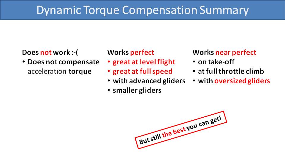
Let’s summarize how SCOUT Dynamic Torque Compensation behaves in the air. It doesn’t do anything to compensate for acceleration torque. This is the momentary amount of torque effect that occurs when the propeller revs up from idle. During this short transition, there is not enough airflow through the frame and the torque will be left uncompensated. So, if you quickly smash the throttle, you will face that uncompensated acceleration torque for a fraction of a second. It will quickly pitch you slightly to the side. But, as soon as the propeller reaches its full speed, there will no longer be any acceleration torque. The propeller will now be generating its own airflow, the windmill behind your back will be compensating for the constant torque from the drag, and you will settle into a nice comfortable neutral position.
It works perfectly at level flight, even with full speed bar. This is especially true with more advanced and smaller gliders.
There are some situations where it doesn’t work perfectly, but it’s still pretty good. On the ground or at very low air speed, the propeller has a higher effective angle of attack. This means that it has higher drag for a given amount of thrust, which leads to some residual uncompensated torque. While running on the ground and taking off, there will be less airflow through the cage than in flight, and you might feel a little torque. So, SCOUT Dynamic Torque Compensation is only near perfect on takeoff. It’s also only near perfect on full throttle climb. It’s plenty good, but there is a little bit of torque left uncompensated. It also doesn’t seem to work completely perfectly with oversized gliders, but it is truly not a problem at all.
Still, we believe that the SCOUT Dynamic Torque Compensation is the best that’s available on the market, and in the next part we will do a full comparison of it to the other methods.
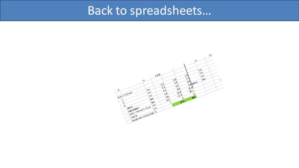
Amusingly, a few years after finalizing the design for the SCOUT Dynamic Torque Compensation, Miro found his original spreadsheet that he used for the aerodynamic calculations. These were the calculations he used for the original design that was a disaster. He went over them again and found two mistakes…two simple stupid mistakes in the formulas in the spreadsheet. Once he fixed those mistakes and then configured it for the size and angle of the spars being used on production SCOUTs, the results suddenly started lining up. They said that the theoretical torque compensation at level flight is 97%, and on a full-power climb is 90%. This seems to match the real performance of the SCOUT in the air.
We have now talked about the various ways for compensating for torque in paramotors. Let’s do the final comparison. –Miro
Part 16: Comparison of Torque Compensation Methods
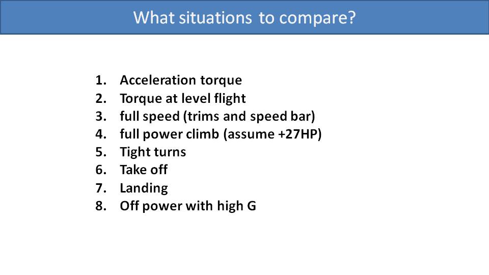
For the final comparison of torque compensation methods, let’s have a closer look on the various situations that you will face in flight.
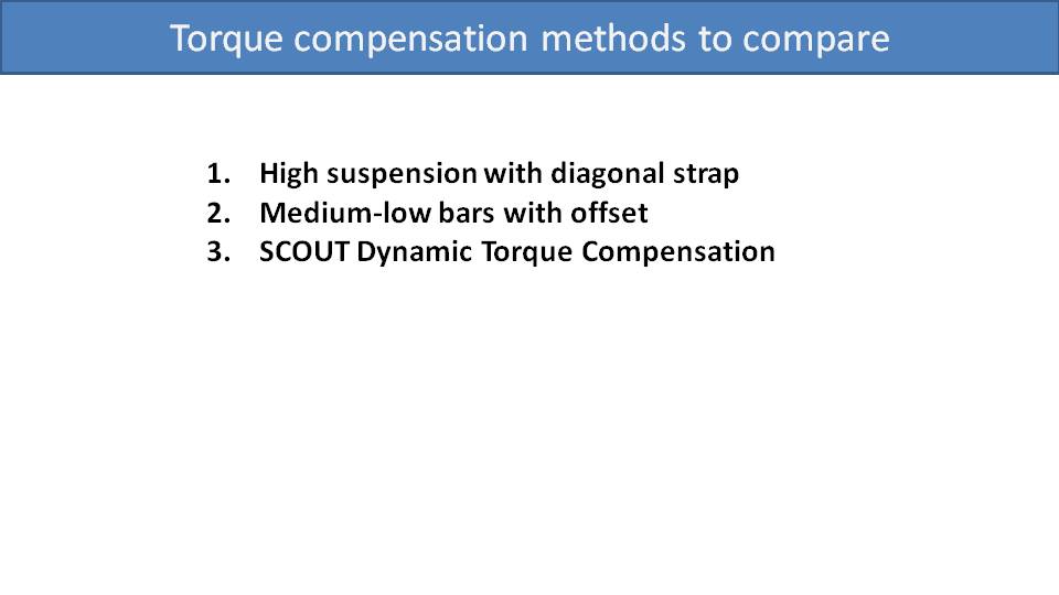
Then, we will analyze each of the three main torque compensation methods:
· High-suspension systems with a diagonal strap
· Medium- or low-suspension systems with bar offsets
· SCOUT Dynamic Torque Compensation
We have the three torque compensation methods listed across the top. Let’s go down through each situation to see how each method handles it.
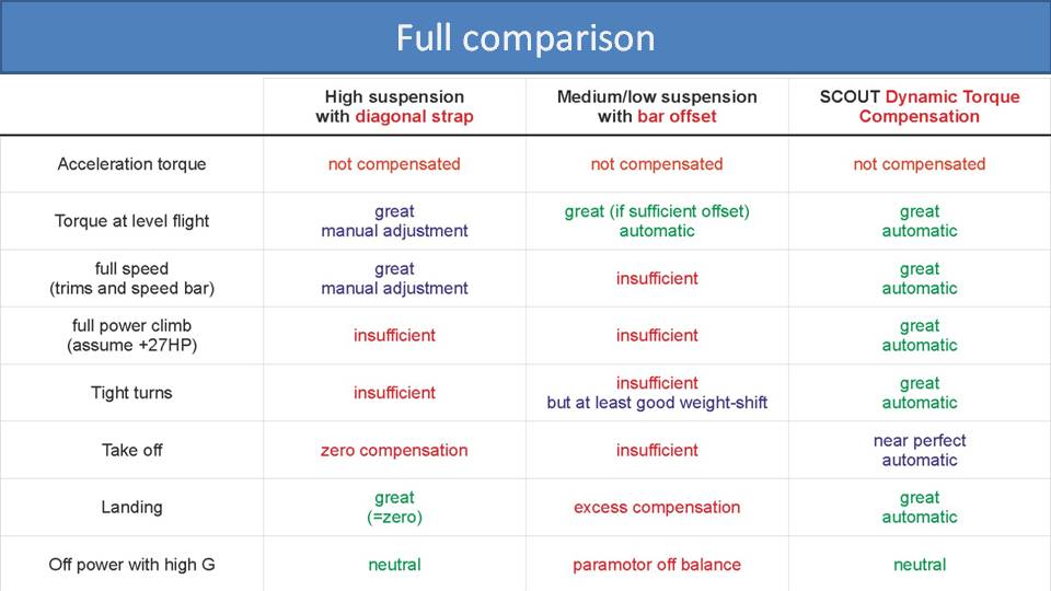
Acceleration Torque: None of the three methods can compensate for acceleration torque at all. It’s not a big deal, so it’s best to just get used to it.
Torque at Level Flight: The torque effect at level flight is the main situation that everyone experiences and is the primary consideration. High-suspension systems can provide very accurate torque compensation for this situation, but you will need to manually adjust the diagonal strap. For medium- and low-suspension systems with bar offsets, their torque compensation will be perfectly balanced if the offsets are designed correctly without any intervention by the pilot. The SCOUT Dynamic Torque Compensation automatically and perfectly compensates for torque at level flight.
Full Speed: If you add enough throttle for level flight with trimmers all the way out and the speed bar pushed, you will be facing a lot more torque. High-suspension systems can compensate for the additional torque by manually adjusting the diagonal strap again. On the medium- and low-suspension systems, there are no in-flight adjustments you can make, so the additional torque will be uncompensated. You will need to constantly weight-shift, hold some brake, or pull your tip steering line to stay straight. With the SCOUT Dynamic Torque Compensation, the compensation increases just as the power, speed and torque of the propeller increases. So, it’s fully automatic and you will still be perfectly balanced at full speed.
Full Power Climb: For the purposes of this chart, let’s assume a more powerful engine like a Moster Plus, Nitro 200 or Black Devil. The diagonal straps on high-suspension systems can help a lot, but they generally cannot completely compensate for torque at full power. They’re good, but not all the way there. Medium- and low-suspension systems have the same issue as when flying at full speed. The bar offsets are tuned for normal level flight and are not adjustable. So, all the additional torque when doing a full-power climb is left uncompensated. The SCOUT Dynamic Torque Compensation automatically increases all the way up to full power and you stay balanced.
Tight turns: When making tight turns or doing any other kind of freestyle flying, you are quickly and constantly going from idle to full throttle and everywhere in between. On high-suspension systems, you will not have time to adjust your diagonal strap in between your maneuvers. You’ll probably have to adjust the diagonal strap for level flight and face excess torque when you go to full power in tight turns. The same situation will occur with medium- and low-suspension systems with bar offsets. They design the torque compensation for level flight. So, when you go into a tight turn at full throttle, the additional torque is left uncompensated. The good news is that they have good weight-shift authority, so you can somewhat compensate for the torque yourself. The SCOUT Dynamic Torque Compensation always generates the right amount of torque compensation regardless of your throttle speed. So, it has excellent performance when playing with the throttle in tight turns and freestyle flying.
Takeoff: You must remove or loosen the diagonal strap on high-suspension systems before launching. So, you will face the full amount of uncompensated torque when taking off and on initial climb-out until you can connect and adjust the strap. Medium- and low-suspension systems with bar offsets provide no torque compensation while you’re running on the ground. As soon as you get lift, then the bar offsets will start to do their job. However, since they are tuned for level flight, you will face some uncompensated torque on your climb-out. The SCOUT Dynamic Torque Compensation is near perfect on takeoff. The air speed across the cage while you’re running on the ground is not quite fast enough to fully compensate for the torque, but it’s close. As soon as you leave the ground and get your air speed up, it becomes perfect again.
Landing: While landing, you will be off throttle and not experiencing any torque from the spinning propeller. So, you will want no torque compensation from the paramotor. On high-suspension systems, you release the diagonal strap when preparing for landing. This will remove all torque compensation and you will be balanced, unless you need to throttle up and go around. Once again, the bar offsets on medium- and low-suspension systems are not adjustable. So, when going to idle for landing, they are now overcompensating for torque and will turn you the other way. As you go to idle for landing, the SCOUT Dynamic Torque Compensation also drops down to minimal torque compensation. You will be perfectly balanced for a smooth landing, and the torque compensation will ramp up again should you need to throttle up and go around.
Off Power for High-G: Flying off-power for high-G maneuvers is referring to acrobatics. Whether you’re performing hardcore acrobatics or just flipping some light wingovers, you’re mostly flying without power. It’s important to have a direct feel and symmetric loading on your glider when performing these dynamic maneuvers. You can disconnect the diagonal strap to remove all torque compensation for acro on high-suspension systems. Then, both the risers will be equally loaded while flying off-power. This is not the case with medium- and low-suspension systems with bar offsets. Once you drop to idle or kill your engine, you will have no torque effect from your engine. But the bar offsets will still be providing compensation and constantly weight-shifting you to the other side, even if you don’t want it. This is undesirable during acrobatic flying, because these pilots will need to alter their weight shift or pull extra brake for every maneuver. This is enhanced in high-G maneuvers when the weight-shift is amplified. So, you will have the benefit of good weight-shift authority with these suspension systems, but the unwanted torque compensation will get in the way. The SCOUT Dynamic Torque Compensation is neutral when off-power and leaves you perfectly balanced for dynamic acro maneuvers. And you still get great weight shift authority.
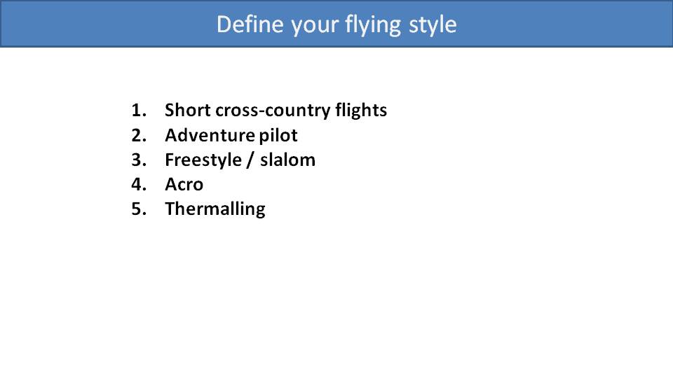
Although that chart looks interesting, what truly matters is how each torque compensation system fits your flying style.

Let’s start with short cross-country flights, which is the largest group of pilots. We can delete the situations that may not be important or crucial for short cross-country flights. This includes acceleration torque, full speed bar, tight turns, and high-G maneuvers. The most important situation for these pilots is torque compensation at level flight and all these methods will perform well.

Adventure pilots fly longer and more demanding cross-country flights, and often find themselves pushing the speed bar. So, torque compensation at level flight as well as at full speed are the crucial situations to consider. All the torque compensation systems do fairly well, but the medium- and low-suspension systems provide other benefits as discussed in part 10.
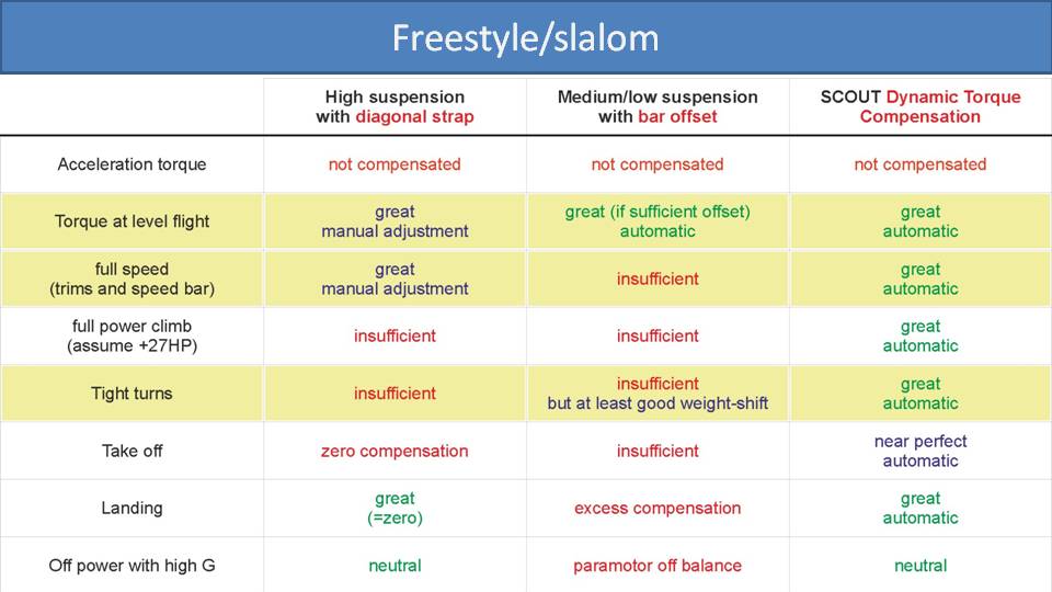
Requirements for torque compensation systems increase dramatically when you get into freestyle and slalom flying. For these pilots, we need to add “tight turns” as another crucial situation. High-suspension systems will have insufficient torque compensation. Weight-shift is much better on medium- and low-suspensions systems, so that will help you compensate for the bar offsets. But the best torque compensation system for tight turns is the SCOUT Dynamic Torque Compensation as its compensation will track with all the rapid throttle changes.
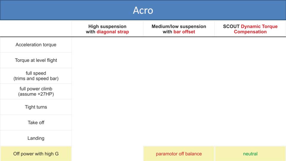
The chart gets simple for acro pilots because they primarily care about having no torque compensation when they go off power. They only use the motor to climb and don’t really care if they climb in circles. Although high-suspension systems would fit the bill once the diagonal strap is removed, they are not really an option for acro pilots due to the lack of weight-shift authority. The bar offsets on medium- and low-suspension systems are a disadvantage because they are always actively weight-shifting to one side. So, an acro pilot would look for a paramotor that has the least amount of bar offset. They would face a lot of excess torque in other flying situations but would be willing to trade that for neutral flight off-power. The SCOUT’s design is with straight and symmetric bars, and completely neutral. Its Dynamic Torque Compensation is minimal when off throttle and provides neutral balance that is perfect for acro pilots.

Finally, torque compensation is not a big consideration for paramotor pilots who are out there to catch thermals. They use the motor to gain altitude. Then they kill the engine and aren’t concerned with torque. So, torque compensation methods are not a major concern to thermalling pilots.
This completes the sections about paramotor suspension systems and torque compensation methods, which are the most important and crucial characteristics of paramotor design. But there are several other aspects to consider which we will delve into in the upcoming sections.
We have now talked about the various ways for compensating for torque in paramotors. Let’s do the final comparison. –Miro
Part 16: Comparison of Torque Compensation Methods

For the final comparison of torque compensation methods, let’s have a closer look on the various situations that you will face in flight.

Then, we will analyze each of the three main torque compensation methods:
· High-suspension systems with a diagonal strap
· Medium- or low-suspension systems with bar offsets
· SCOUT Dynamic Torque Compensation

We have the three torque compensation methods listed across the top. Let’s go down through each situation to see how each method handles it.
Acceleration Torque: None of the three methods can compensate for acceleration torque at all. It’s not a big deal, so it’s best to just get used to it.
Torque at Level Flight: The torque effect at level flight is the main situation that everyone experiences and is the primary consideration. High-suspension systems can provide very accurate torque compensation for this situation, but you will need to manually adjust the diagonal strap. For medium- and low-suspension systems with bar offsets, their torque compensation will be perfectly balanced if the offsets are designed correctly without any intervention by the pilot. The SCOUT Dynamic Torque Compensation automatically and perfectly compensates for torque at level flight.
Full Speed: If you add enough throttle for level flight with trimmers all the way out and the speed bar pushed, you will be facing a lot more torque. High-suspension systems can compensate for the additional torque by manually adjusting the diagonal strap again. On the medium- and low-suspension systems, there are no in-flight adjustments you can make, so the additional torque will be uncompensated. You will need to constantly weight-shift, hold some brake, or pull your tip steering line to stay straight. With the SCOUT Dynamic Torque Compensation, the compensation increases just as the power, speed and torque of the propeller increases. So, it’s fully automatic and you will still be perfectly balanced at full speed.
Full Power Climb: For the purposes of this chart, let’s assume a more powerful engine like a Moster Plus, Nitro 200 or Black Devil. The diagonal straps on high-suspension systems can help a lot, but they generally cannot completely compensate for torque at full power. They’re good, but not all the way there. Medium- and low-suspension systems have the same issue as when flying at full speed. The bar offsets are tuned for normal level flight and are not adjustable. So, all the additional torque when doing a full-power climb is left uncompensated. The SCOUT Dynamic Torque Compensation automatically increases all the way up to full power and you stay balanced.
Tight turns: When making tight turns or doing any other kind of freestyle flying, you are quickly and constantly going from idle to full throttle and everywhere in between. On high-suspension systems, you will not have time to adjust your diagonal strap in between your maneuvers. You’ll probably have to adjust the diagonal strap for level flight and face excess torque when you go to full power in tight turns. The same situation will occur with medium- and low-suspension systems with bar offsets. They design the torque compensation for level flight. So, when you go into a tight turn at full throttle, the additional torque is left uncompensated. The good news is that they have good weight-shift authority, so you can somewhat compensate for the torque yourself. The SCOUT Dynamic Torque Compensation always generates the right amount of torque compensation regardless of your throttle speed. So, it has excellent performance when playing with the throttle in tight turns and freestyle flying.
Takeoff: You must remove or loosen the diagonal strap on high-suspension systems before launching. So, you will face the full amount of uncompensated torque when taking off and on initial climb-out until you can connect and adjust the strap. Medium- and low-suspension systems with bar offsets provide no torque compensation while you’re running on the ground. As soon as you get lift, then the bar offsets will start to do their job. However, since they are tuned for level flight, you will face some uncompensated torque on your climb-out. The SCOUT Dynamic Torque Compensation is near perfect on takeoff. The air speed across the cage while you’re running on the ground is not quite fast enough to fully compensate for the torque, but it’s close. As soon as you leave the ground and get your air speed up, it becomes perfect again.
Landing: While landing, you will be off throttle and not experiencing any torque from the spinning propeller. So, you will want no torque compensation from the paramotor. On high-suspension systems, you release the diagonal strap when preparing for landing. This will remove all torque compensation and you will be balanced, unless you need to throttle up and go around. Once again, the bar offsets on medium- and low-suspension systems are not adjustable. So, when going to idle for landing, they are now overcompensating for torque and will turn you the other way. As you go to idle for landing, the SCOUT Dynamic Torque Compensation also drops down to minimal torque compensation. You will be perfectly balanced for a smooth landing, and the torque compensation will ramp up again should you need to throttle up and go around.
Off Power for High-G: Flying off-power for high-G maneuvers is referring to acrobatics. Whether you’re performing hardcore acrobatics or just flipping some light wingovers, you’re mostly flying without power. It’s important to have a direct feel and symmetric loading on your glider when performing these dynamic maneuvers. You can disconnect the diagonal strap to remove all torque compensation for acro on high-suspension systems. Then, both the risers will be equally loaded while flying off-power. This is not the case with medium- and low-suspension systems with bar offsets. Once you drop to idle or kill your engine, you will have no torque effect from your engine. But the bar offsets will still be providing compensation and constantly weight-shifting you to the other side, even if you don’t want it. This is undesirable during acrobatic flying, because these pilots will need to alter their weight shift or pull extra brake for every maneuver. This is enhanced in high-G maneuvers when the weight-shift is amplified. So, you will have the benefit of good weight-shift authority with these suspension systems, but the unwanted torque compensation will get in the way. The SCOUT Dynamic Torque Compensation is neutral when off-power and leaves you perfectly balanced for dynamic acro maneuvers. And you still get great weight shift authority.

Although that chart looks interesting, what truly matters is how each torque compensation system fits your flying style.
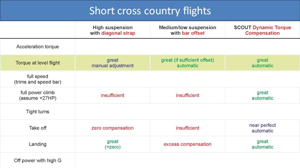
Let’s start with short cross-country flights, which is the largest group of pilots. We can delete the situations that may not be important or crucial for short cross-country flights. This includes acceleration torque, full speed bar, tight turns, and high-G maneuvers. The most important situation for these pilots is torque compensation at level flight and all these methods will perform well.
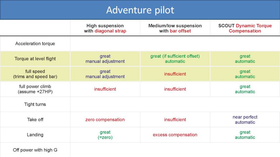
Adventure pilots fly longer and more demanding cross-country flights, and often find themselves pushing the speed bar. So, torque compensation at level flight as well as at full speed are the crucial situations to consider. All the torque compensation systems do fairly well, but the medium- and low-suspension systems provide other benefits as discussed in part 10.

Requirements for torque compensation systems increase dramatically when you get into freestyle and slalom flying. For these pilots, we need to add “tight turns” as another crucial situation. High-suspension systems will have insufficient torque compensation. Weight-shift is much better on medium- and low-suspensions systems, so that will help you compensate for the bar offsets. But the best torque compensation system for tight turns is the SCOUT Dynamic Torque Compensation as its compensation will track with all the rapid throttle changes.

The chart gets simple for acro pilots because they primarily care about having no torque compensation when they go off power. They only use the motor to climb and don’t really care if they climb in circles. Although high-suspension systems would fit the bill once the diagonal strap is removed, they are not really an option for acro pilots due to the lack of weight-shift authority. The bar offsets on medium- and low-suspension systems are a disadvantage because they are always actively weight-shifting to one side. So, an acro pilot would look for a paramotor that has the least amount of bar offset. They would face a lot of excess torque in other flying situations but would be willing to trade that for neutral flight off-power. The SCOUT’s design is with straight and symmetric bars, and completely neutral. Its Dynamic Torque Compensation is minimal when off throttle and provides neutral balance that is perfect for acro pilots.
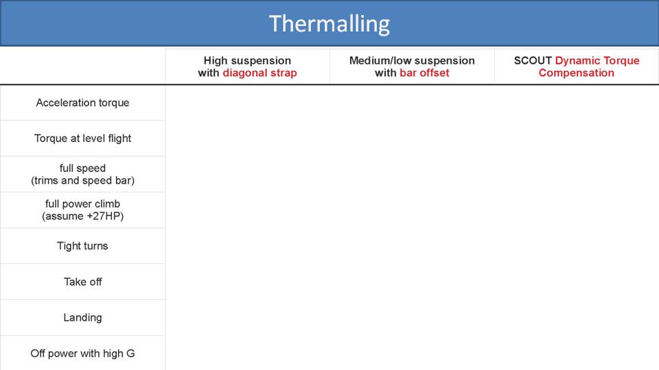
Finally, torque compensation is not a big consideration for paramotor pilots who are out there to catch thermals. They use the motor to gain altitude. Then they kill the engine and aren’t concerned with torque. So, torque compensation methods are not a major concern to thermalling pilots.
This completes the sections about paramotor suspension systems and torque compensation methods, which are the most important and crucial characteristics of paramotor design. But there are several other aspects to consider which we will delve into in the upcoming sections.
A few years ago, a well-respected pilot from the United States was reviewing the SCOUT. After his test flight, we were discussing the behavior of the paramotor, and it became apparent that he was confusing one of its behaviors with the torque effect. It was not torque he was noticing, but the gyroscopic effect. This is difficult to observe and even more difficult to explain, so wish us luck as we try. –Miro
Part 17: Gyroscopic Effect on Paramotors
Let’s dive into the strange behavior of the gyroscopic effect and how it manifests in paramotors.
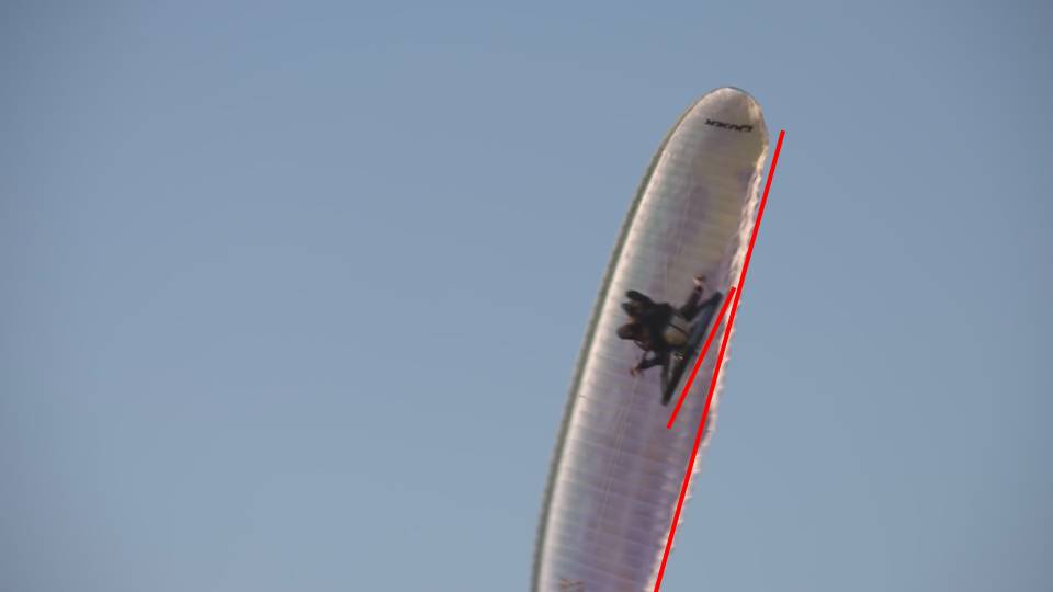
Looking at this shot of a paramotor turning from below, we see a strange offset angle between the paramotor and the glider. There is nothing wrong with the paramotor or how the pilot is controlling it. It’s just physics.
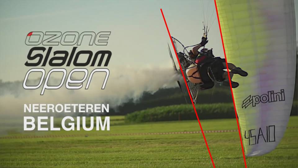
Now, here is a video of world champion pilot, Alex Mateos, doing a wing-tip touch. Again, you can see how he has a slight rotation as compared to his glider during this ultra-tight turn. This behavior is caused by the gyroscopic effect.
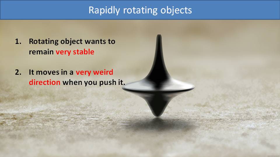
Let’s recall this picture of a spinning top from part 12. A rapidly rotating object wants to remain stable in that position. But, if you apply a force to it, the resulting behavior is strange. It will move in a different direction than the applied force.
One of the best explanations and demonstrations of this effect was done by Professor Walter Lewin from MIT. Let’s have a closer look.
In this video, you can see Professor Lewin hangs a rapidly spinning wheel from just one side of its axle. Instead of falling over, it starts to rotate around its hang point.
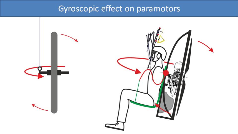
Here is a drawing of Professor Lewin’s spinning wheel suspended on the left. So, gravity will apply a rotational force to the right at the top of the spinning wheel and a rotational force to the left at the bottom. But, due to the gyroscopic effect, this translates into a rotational force in the horizontal direction. So, the spinning wheel doesn’t fall, it rotates about its hang point.
The exact same thing happens when you go to full power on a paramotor. At constant level flight, the paramotor will be suspended from its hang points in a neutral and stable manner. But, when you apply full throttle, the paramotor will lean back. This will apply a rotational force to the paramotor similar to Professor Lewin’s spinning wheel. The top rotates backwards, and the bottom rotates forwards. Due to the gyroscopic effect, it will cause the paramotor to rotate around its vertical axis, just as we saw in those paramotor videos.
While it’s easy to see the effect in the videos, it’s not intuitive to understand. We’ll do our best to explain.
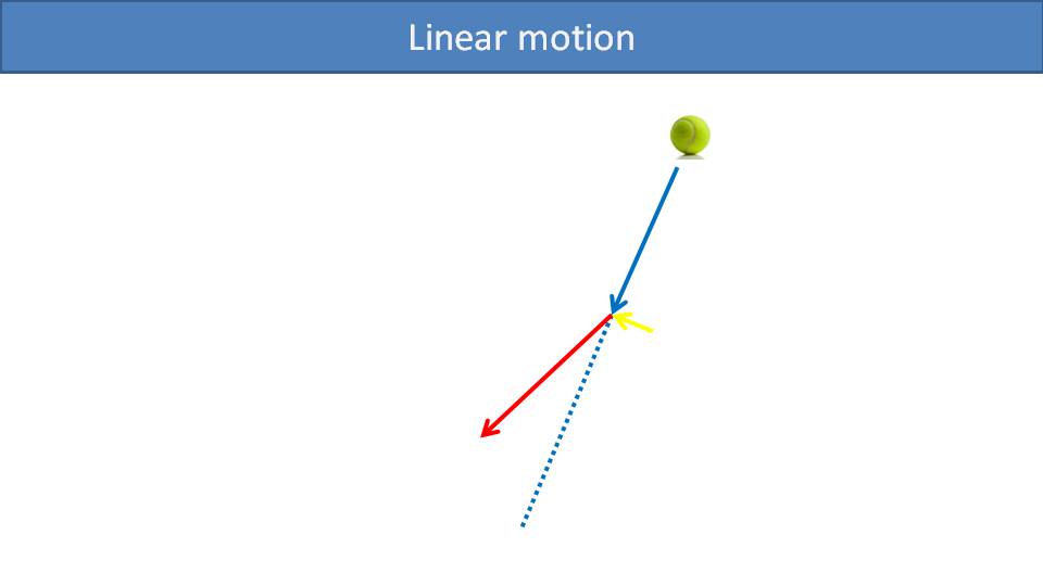
Let’s start with linear motion first. Assume we have a ball moving in the direction of the arrow. When it reaches the end of the arrow, we apply force to its side.
Because of the force applied, the ball’s direction of travel will change.
Instead of moving in a straight line, the dotted line, it will now divert into a new direction indicated by the red arrow. Next, let’s turn the linear motion of the ball into the rotation motion of a propeller.
Imagine the tip of the propeller as our ball that continues to spin in circles. Once the ball reaches the bottom of the cage, we apply force from the back.
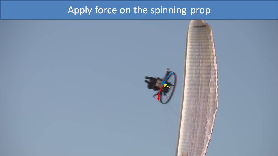
It will start changing the direction of the ball towards the front of the cage. This direction change doesn’t fully take effect until 90 degrees later in the spin. At that point it will be a forward push on the right side of the paramotor. The opposite happens at the top of the cage, resulting in a backward pull on the left side of the paramotor. That’s why we see the paramotor turning to the right a bit. This is obviously a simplified explanation, but here are some great videos to watch if you want to learn more:
· The Gyro Effect Explained Without Math
· Veritasium’s Gyroscopic Procession
· Professor Walter Lewin’s Full Lecture
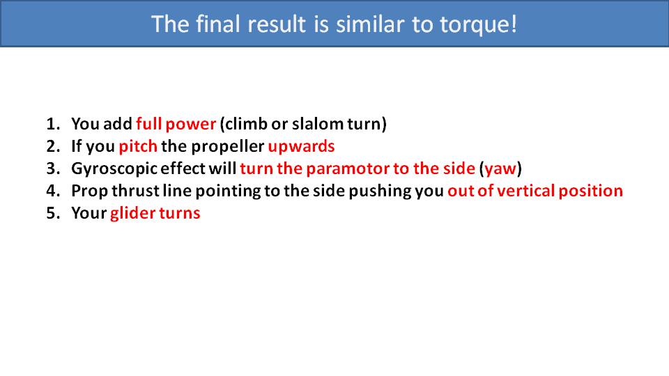
To summarize, let’s assume a level flight at constant RPM. If we go to full power for climb-out or a tight slalom turn, it will pitch the paramotor upwards. The gyroscopic effect will turn the pilot and the paramotor to one side. The twisted thrust line will push the paramotor away from the center of the glider and cause it to turn. As both the gyroscopic effect and the torque effect cause the glider to turn to the same direction, it is easy to confuse the two. This is exactly what that very respectable pilot was doing when he was testing the SCOUT. He was looking up at the glider, going to full throttle, and observing how much the angle between his paramotor and his glider was changing. In this case, he was observing the gyroscopic effect and not the torque effect.
What can you do about it? Unfortunately, not much. You can use a lighter propeller, which will reduce the gyroscopic effect due to the reduced rotational mass. In fact, this is why it seems that larger and more powerful engines have more gyroscopic effect. It’s not because the engine is larger. It’s because larger engines are usually paired with larger and heavier propellers, often with more blades, to make use of the added power.
The other thing you can do is just to get used to it. It’s not horrible and most pilots don’t even notice it, because they don’t fly completely off and then on throttle very often. Most of their flights are easy cruising flights where you won’t observe this effect at all.
Accordion Content
There is a stupid mistake that you can make on the ground that could easily kill you once you’re in the air. Being reclined is extremely dangerous. Let’s explain why and how to prevent those accidents. –Miro
Part 18: The Danger of Reclined Paramotors
First, let’s watch some paramotor crashes that were unnecessary.
All these videos have the same issue in common. The trouble starts when the paramotor and pilot start to twist to the side. Then, the glider starts to turn sharply, and the pilot reacts with heavy brake input. Despite staying on full throttle, the glider stalls, and the pilot falls on his back.
Let’s look at this particular accident step by step. As the pilot jumps into his harness, notice how he is reclined backwards. Then, the paramotor starts to twist and becomes severely twisted under the glider. Eventually the thrust line is pointed to the left and not forward. He loses all forward thrust, and the new thrust line pushes him to the left, which causes the glider to turn to the right. To compensate, the pilot starts pulling a lot of left brake. This eventually stalls the glider, and he falls out of the sky.
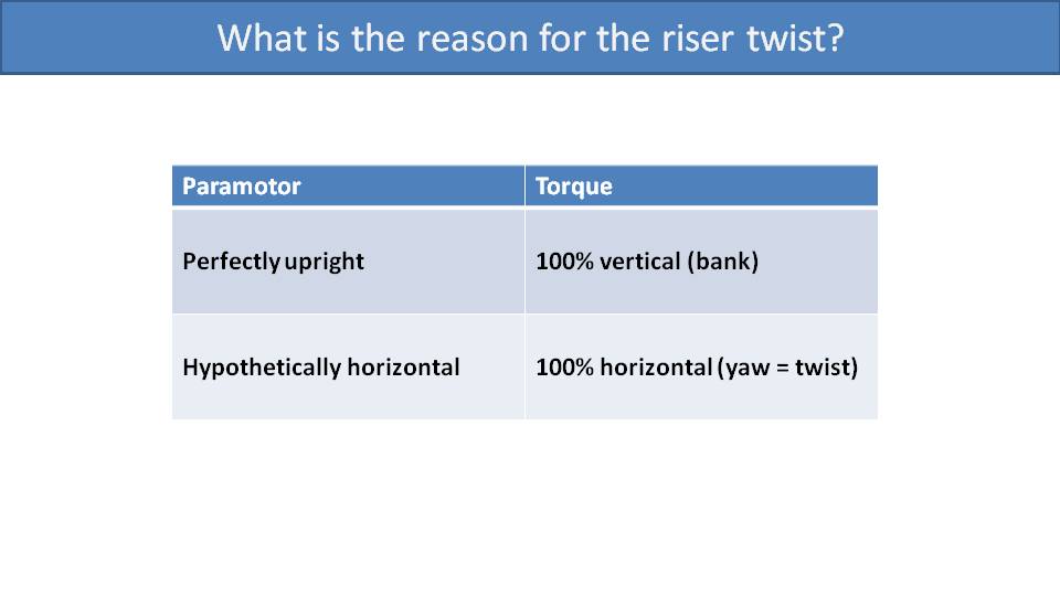
It’s obvious that all these pilots got into trouble by getting twisted underneath the glider. At that point, they should have immediately let go of the throttle and hoped for the best landing possible. But the big question is: Why did they twist in the first place? The reason is from an incorrect suspension adjustment.
If the paramotor and propeller were vertical, then all the torque would be on the vertical plane. This would just bank the glider to the right in a normal flying position.
Imagine a hypothetical situation where the paramotor is completely horizontal. Then, the torque would be twisting the pilot on the horizontal plane instead.
In the video, we noticed that the pilot was leaning backwards significantly. He was in between the vertical and horizontal positions, so the torque effect would also be a mix of horizontal and vertical twisting forces. This caused him to twist up and to the left. He then stayed at full throttle, which continued to twist him up and to the left even more. His new thrust line pushed him to the left of the glider’s centerline, causing it to bank heavily to the right. If you find yourself starting to get into this situation, the remedy is to immediately let go of the throttle.
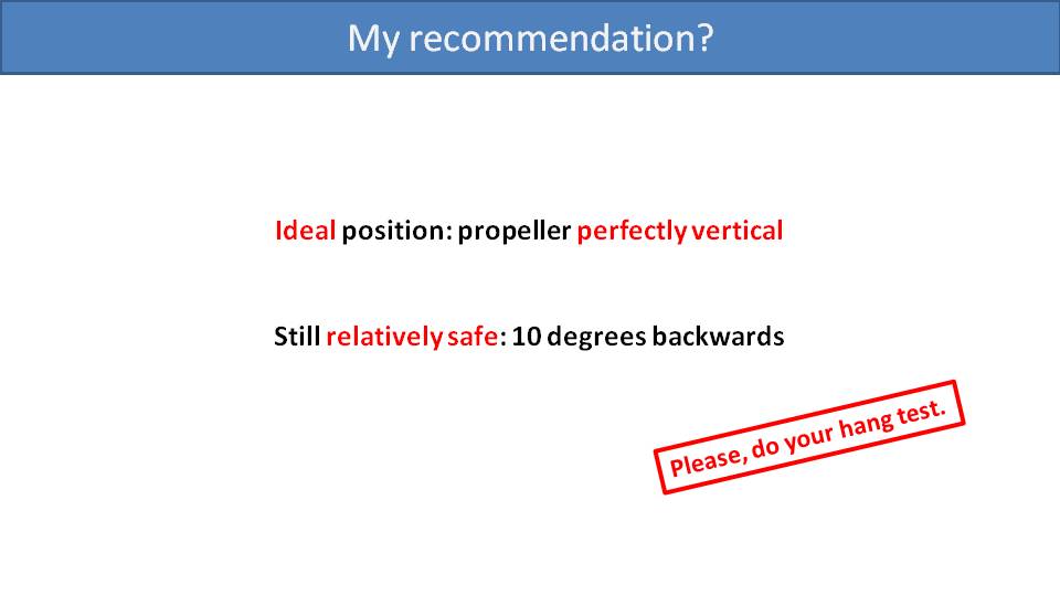
The more you are leaned backwards, the more of the dangerous horizontal component of the torque effect there is. This horizontal component is the reason for the riser twist. The easy and obvious way to prevent the horizontal, riser-twisting component of the torque effect is to ensure the propeller is perfectly vertical. Yet, most pilots don’t adjust their paramotors this way. The reason is that it’s uncomfortable to fly in a perfectly upright position for long. They adjust their hang points to recline them and make them more comfortable in the air. Most manufacturers recommend setting the suspension’s hang point such that the pilot reclines at an angle of about 10 degrees. It’s not ideal, but it’s comfortable enough and sufficiently safe.
Before flying a new paramotor, we strongly recommend that you do a hang test to make sure that you are not reclining too much. It’s not just safer to keep the propeller perfectly vertical, it can also make you fly faster. We’ll investigate in the next part.
I’ve warned you that reclining too much is dangerous. Reclining within 10-12 degrees is pretty safe, but it’s also slower and more inefficient. –Miro
Part 19: Reclining is Inefficient
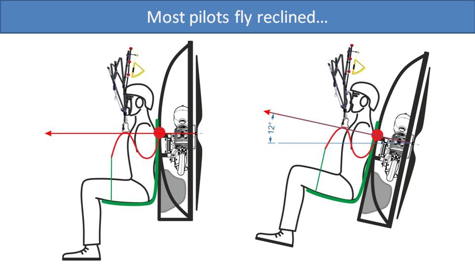
In the last part, we concluded that adjusting your hang point such that the propeller is completely vertical is the safest way, but it’s not comfortable. So, most pilots adjust their paramotors such that they recline by about 10 to 12 degrees. Let’s see what this does to the thrust line.
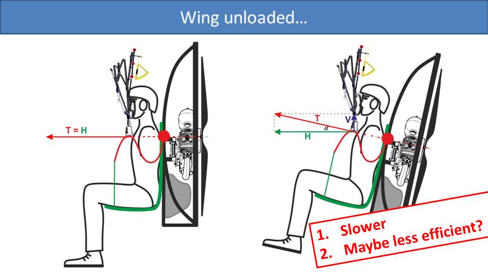
When reclining your paramotor, its thrust line will now be pointing slightly upwards. We can split this force into two vectors. One is the horizontal thrust component that will be used for maintaining level flight, and the other vector is its vertical component pushing you upwards. This vertical component will effectively make you lighter and unload the wing. A more lightly loaded wing will fly slower. So, reclining your paramotor makes your fly slower. But is it more efficient or less efficient?
If you’re flying slower and you’re lighter on your glider, then you need less horizontal thrust to maintain level flight. But does that mean that the total thrust required is much less? We’ll need to analyze it to find out.
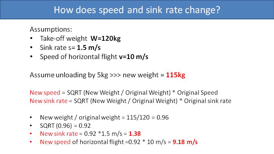
Let’s make some assumptions to help us determine what’s happening. We’ll assume that your total weight, including your paramotor is 120 kg, with a sink rate of 1.5 m/s, and a horizontal speed of flight of 10 m/s.
Now, if we assume that the vertical thrust component unloads your glider by 5 kg, then that makes your effective weight 115 kg. To calculate the new speed and the new sink rate, we can use these formulas:
New Speed = (New Weight / Original Weight)2 * Original Speed
New Sink Rate = (New Weight / Original Weight)2 * Original Sink Rate
The new speed and sink rate are the original speed and sink rates times the square of the ratio of the new weight versus the original weight. The square of the ratio of the new weight versus the old weight is 0.92. So, we can multiply 0.92 times the original sink rate and speed to get a new sink rate of 1.38 m/s and a new speed of 9.18 m/s.
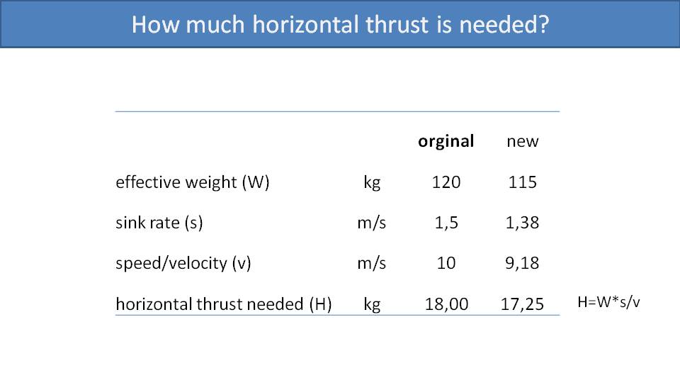
Because of the lower sink rate and the lower speed, we will need less horizontal thrust to maintain level flight. We can use this formula to calculate that thrust:
Thrust = Weight * Sink Rate / Speed
Using this formula and the original numbers, we calculate 18 kg of thrust needed for level flight. Then, using the new numbers while being unloaded down to 115 kg, this calculates to only needing 17.25 kg of thrust for level flight.
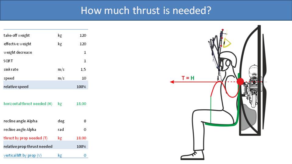
Let’s go back and use these horizontal thrust numbers to calculate the total thrust needed. In the first scenario, where the propeller is perfectly vertical, the total thrust needed is the same as the horizontal thrust needed because there is no vertical component. So, the total thrust required by the propeller is 18 kg.
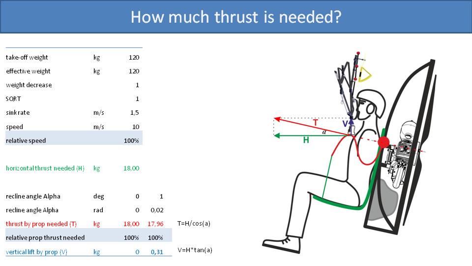
Now if you recline, then some of the propeller’s thrust is used as vertical lift. Starting at reclining just one degree, some geometric calculations tell us that 0.31 kg of the propeller’s thrust is converted into vertical lift. As we learned, this 0.31 kg of vertical lift will make you effectively lighter, requiring less thrust to maintain level flight. This leads us to a circular relationship as reducing the thrust starts us back at the beginning of our formulas. So, those three numbers, the effective weight, the horizontal thrust needed, and the vertical lift by the propeller are all dependent on each other. To get to an answer, we did some iterative calculations using a spreadsheet.
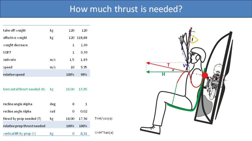
Here is the output of that spreadsheet that shows us the results when reclining from 0 degrees all the way up to 12 degrees. Let’s look at the 12-degree example. Due to the unloading of the glider, the speed of flight decreases to only 94% of the original speed. To achieve that we need less horizontal thrust. But, to get that horizontal thrust at that angle, the total thrust is still 99% of the original thrust. This means that we are using 99% of the same power as not being reclined to only go 94% of its speed.
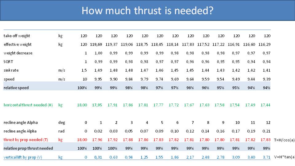
In summary, with the same glider, same engine, and same pilot, if you recline by 12 degrees, your overall speed will be reduced by 6% while your engine RPM drops by only 1%. This isn’t a good deal, especially if we can figure out a way for the pilot to be comfortable while keeping the propeller completely vertical.
Some paramotors fly faster in others. To understand why, we need to pay attention to one specific detail in the frame’s geometry. –Miro
Part 20: Why Some Paramotors Fly Faster Than Others
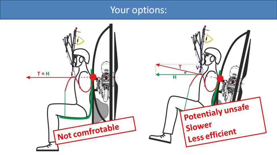
Previously, we said that a perfectly vertical propeller is ideal for safety. But then we said no one flies this way because it’s uncomfortable to sit completely upright. So, most pilots choose to recline, even though it’s less safe, slower, and less efficient.
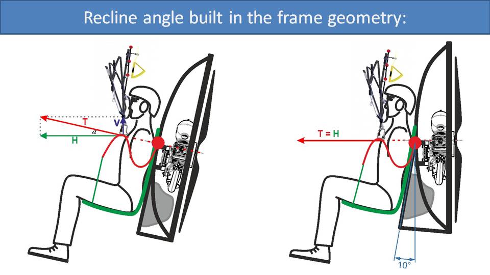
Can we compensate in the design of the paramotor frame? The design on the left is the simplest and most common. The vast majority of paramotor designs are like this. They are simple, linear frames that mount the harness and pilot on the front, and the engine, propeller, and fuel tank on the back. Then, the pilot adjusts the carabiner positions such that they’re reclined to a comfortable degree that is hopefully not too dangerous.
The other option is to build the recline angle into the frame, like the design on the right. Here, there is a 10-degree tilt between the pilot’s back and the propeller. With this design, the propeller is in its most efficient, safest, and fastest position, while the pilot is still comfortably reclined. There are a few paramotors that incorporate this angle in their design, most notably, the SCOUT. Clearly, while in flight, this is the best configuration with the optimal propeller position and pilot position.
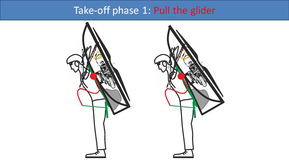
However, there are some disadvantages while on the ground. Let’s start with the beginning phase of takeoff. As you start your run, you lean forward to pull the glider off the ground. The cage is tilted an additional 10 degrees and touches your risers a bit longer as you pull your glider up. There is not a significant side effect to this change, so both designs are relatively equal during this phase.
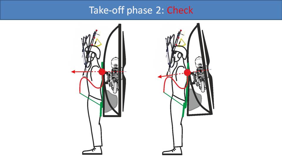
After you pull your glider up above your head and start running, perhaps with a quarter throttle to help maintain speed, you may want to look up and check your glider. With the frame tilted, there will be less room between the top of your frame and your head to look up. So, the visibility is not as good, and you may have to look more towards the side. Once you have checked your glider and everything is good, it’s time for the next phase, the full-throttle run.
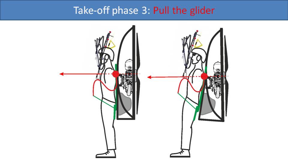
In this phase, you must take care to have good posture. Because of the added angle between your back and the propeller, if you lean forward at all, the thrust will push you into the ground. You must take special care to try to lean backwards a bit while running at full throttle. But, with good technique, the added angle is not an issue.
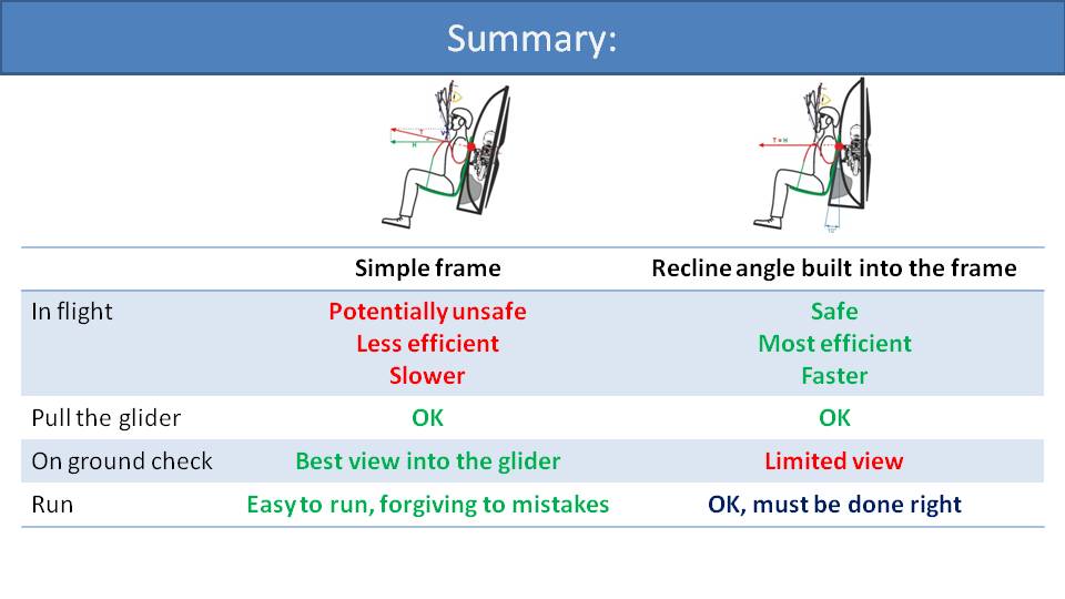
Let’s do the final comparison of both frame geometry options, the simple frame and the frame with the recline angle built in. In flight, building the recline angle into the frame is safer, more efficient, and faster than the simple frame. However, there are some disadvantages on the ground. First, your view into the glider is limited. You can see the tips easily, but the center of the glider is more difficult. Once you’re in the air and seated, then you can see the whole glider again. Secondly, your posture must be good on your full-throttle run. The simple frame geometry is more forgiving of beginner mistakes while launching.
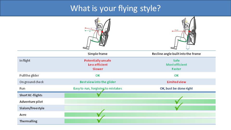
Depending on your skill and your flying style, one of these designs could be better for you than the other. If you mostly fly short cross-country flights, then speed and efficiency may not be as important, and the simple frame could be better. If you are an adventure pilot, then speed and efficiency are critical, and you will probably prefer a frame with the recline angle built in. This is also true for slalom and freestyle pilots who need access to all the thrust that an engine can give. Acro and thermalling pilots are not too concerned with speed and efficiency and may prefer the simple frame to make ground handling easier.
We designed the SCOUT with the recline angle built in, because we wanted to optimize it for flying. We wanted our pilots to have the best experience in the air, and that the disadvantages could be overcome with good technique.
We have a confession to make. We’ve invented a paramotor frame that puts a new twist on recline angle tradeoffs. –Miro
Part 20.2: Introducing Variable Frame Geometry
Previously we mentioned there are two frame designs when it comes to pilot’s recline angle. But there is a third: The SCOUT NXT. It has a different geometry that incorporates some fantastic innovations.

As we recall from Part 20, there are two options that paramotor designers can choose from regarding how the pilot reclines in flight. The parallel design on the left uses a simple linear frame where the propeller is parallel with the pilot’s back. It’s less efficient, potentially unsafe, and slower in the air. However, it’s better for ground handling. The SCOUT uses the design on the right where the recline angle is built into the frame. We chose this option because we prioritized safety, efficiency, and speed. We wanted the best experience in the air. But we had to accept the disadvantages with regards to ground handling.
We didn’t want to leave well enough alone, so we started exploring options.
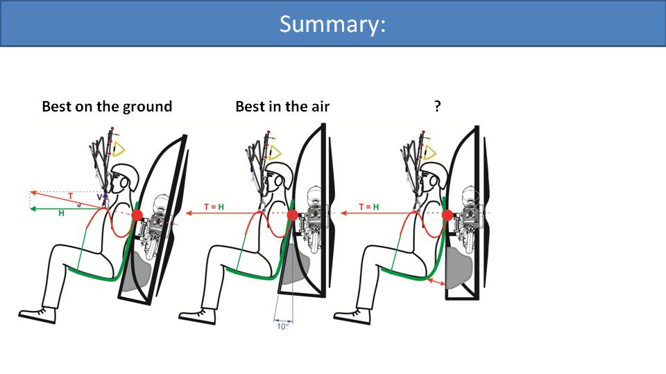
One solution is to detach the harness at the bottom. Then, the harness could recline away from the paramotor frame while in the air. Presumably, the pilot would have the advantage of the parallel frame on the ground and still be reclined in the air.
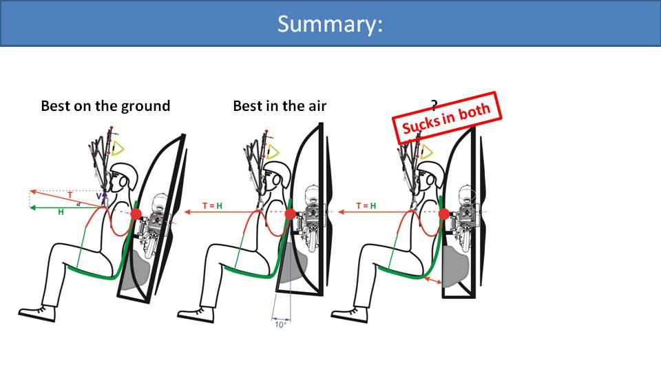
Unfortunately, this design has serious flaws, both on the ground and in the air. This is a result of the harness being completely detached from the frame at the bottom. While running during your final phase of takeoff, if the harness is detached at the bottom, the torque will twist the whole frame on your back as you go to full-throttle. You will have less feedback from the glider, less feedback from the motor and it will all feel sloppy. The same is true in the air. If you quickly add throttle, the motor won’t act as a single unit with the pilot. Also, if the pilot tries to use some weight-shift, the bottom of the harness will just sway the other way.
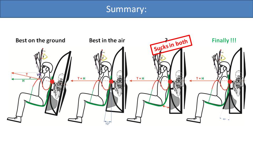
So, we came up with a solution where the harness remains attached to the frame, and the frame changes its geometry. We call this solution “variable frame geometry”.
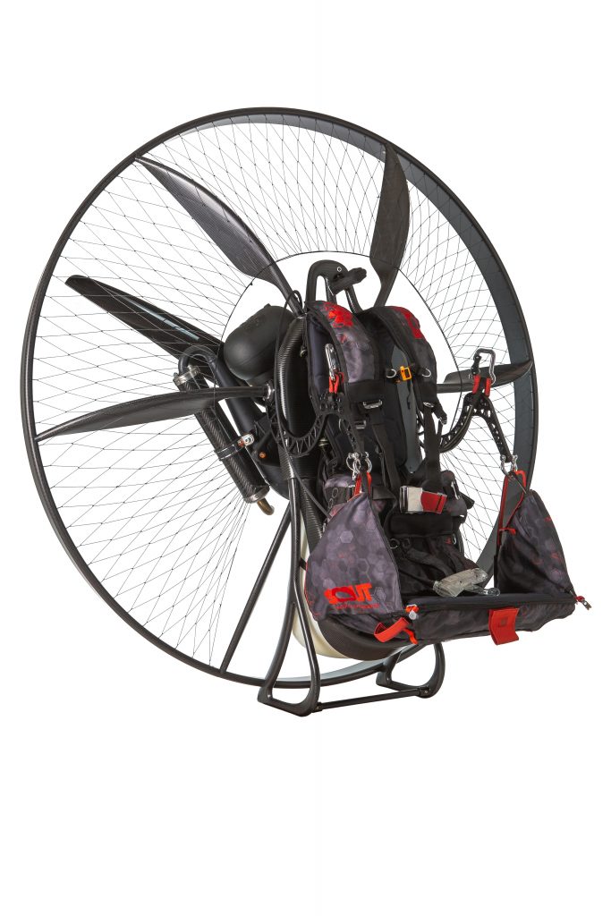
To see variable frame geometry in action, let’s look at the SCOUT NXT.
The bottom section of the backrest can swing in and out. When standing on the ground, your butt pushes this section backwards, and you will be parallel with the propeller and frame. So, it will be easier to look up into your glider, easier to ground-handle, and easier to run at full-throttle for a nice takeoff. But, the bottom of the harness is still attached to the frame, so the torque can’t twist the frame on your back.
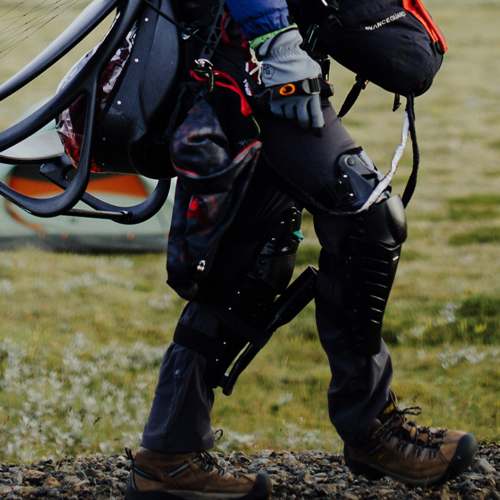
Right after takeoff, when the risers pull the bars up, they will pull the seat forward and away from the frame. That will pivot the seatback forward, creating a nicely reclined position for a comfortable flight. So, we get great ground-handling and great comfort and performance in the air without the previously mentioned disadvantages.
Miro got this idea on a flight from Dubai to Bratislava on an Airbus 320 a few years back. He noticed its interesting reclining mechanism, where the seat bottom slides forward instead of the seat back tilting into the person behind him. So, he put this design into the SCOUT NXT.
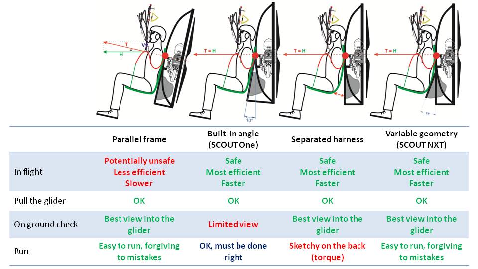
Here is our summary of the four designs we discussed here. The parallel frame is ideal for ground-handling, but suboptimal in the air. Frames with a built-in recline angle, like the SCOUT One, is ideal in the air and less than perfect on the ground. The separated harness seems to be a solution, but it feels sloppy and takes away pilot feedback. The SCOUT NXT combines the benefits of both the parallel frame as well as the built-in angle frame without the disadvantages of either of them or the separated harness design.
Some paramotors are easier to get into the seat, and some are easier to get out of the seat. It’s all about the harness design. –Miro
Part 21: Getting In and Out of the Harness
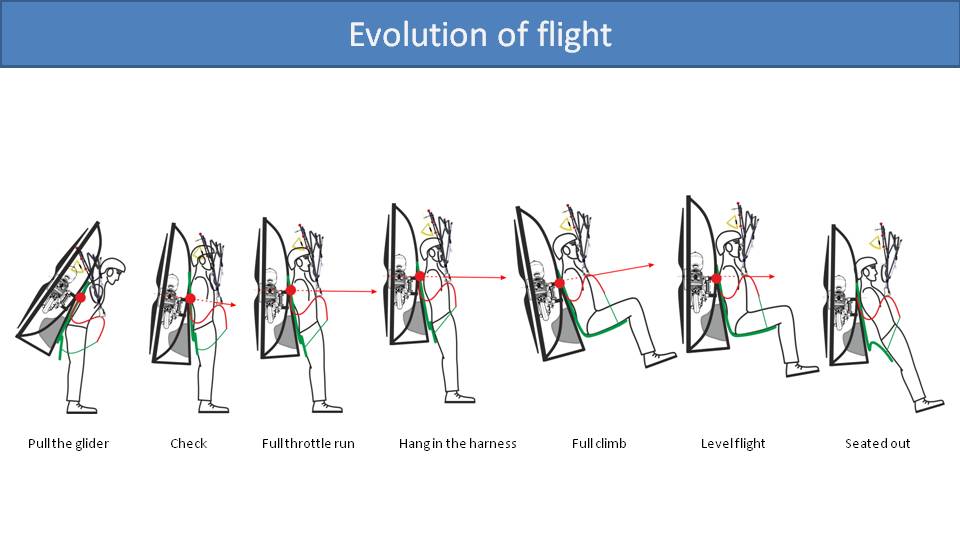
The harness design is not only important for comfort in flight, but all the phases of flight. We’ll go through each phase to understand the implications.
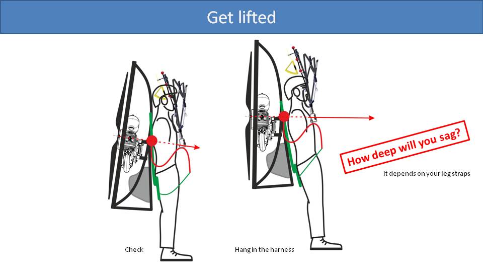
Let’s start with takeoff. As you’re starting your run, perhaps you’re applying about a quarter throttle, checking your glider, but not actually getting any lift. At this point, the paramotor is hanging on the shoulder straps, a bit lower on your body. But it’s completely different a few seconds later after you get lifted off the ground. Instead of the paramotor hanging on your shoulders, you are hanging from the paramotor by your leg straps. In both cases, the seat board is folded up against the paramotor frame. After you are in the air, the glider is trying to lift the bars up into their position which would then pull the seat board up to be horizontal. However, while your legs are pushing the seat board down, the bars can’t pull the seat board up. This is affected by how low you are hanging in the harness, which depends on the position and length of the leg straps. If the leg straps are low or are too loose, you will hang low in the harness. It’s not a big issue right after takeoff, but it will be shortly thereafter.
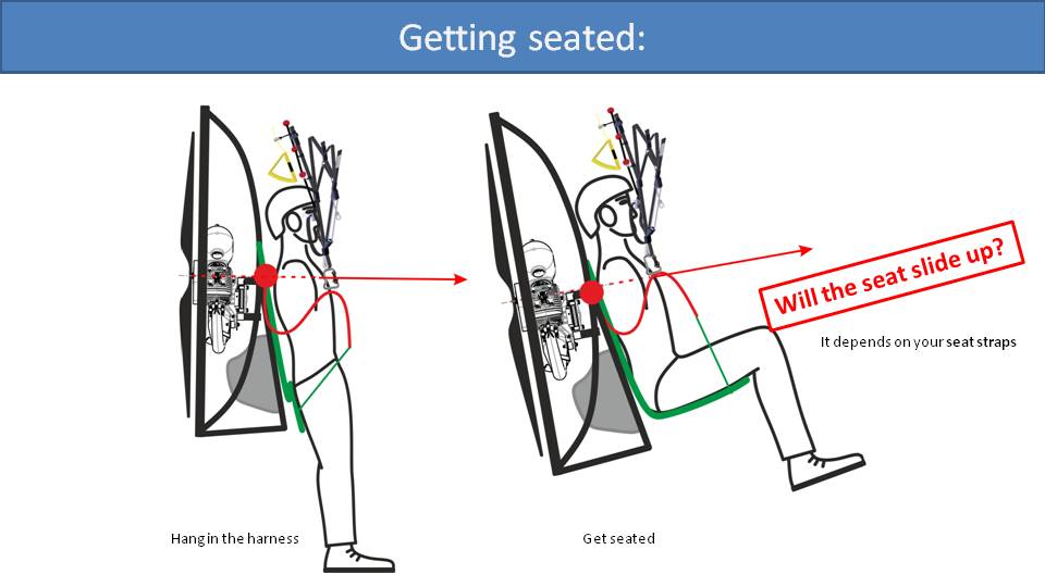
Now it’s time for the transition between hanging in the harness by your leg straps to getting into a seated position. Ideally, you would just need to lift your knees and remove pressure from the seat board, which would allow the bars to pull the seat board up horizontally beneath your legs. The crucial point for the success of this maneuver is where the green strap connects with the seat board and where that point is relative to your butt. If your butt is lower than that point, then raising your legs doesn’t alleviate the pressure on the seat board, and it won’t pop up. In that case, you’ll need to stow your brakes, reach down, and push the seat board down under your legs. Some paramotor manufacturers will add a step-up bar or strap that you can step in and raise your body to get into the seat.
However, if your butt is higher than that crucial point where the seat board strap meets the seat board, then you can just raise your knees and allow the seat board to slide up underneath your legs. The relative position between your butt and this crucial point is determined by two factors. The first is the position and length of the leg straps which influences how low you sag in the harness. The second is the position of the seat board strap itself.
For the purposes of getting into your seat, the ideal configuration is to have your leg straps high and tight, so you don’t sag. Next, have the seat board strap connected at the end of the seat board. Then, when you raise your legs, the strap has lots of leverage and little resistance to pull the seat board up. Notice on the left, the bar is down while the seat board is locked down. But, when you raise your knees and the seat board pops up, the bar rises to its natural position.
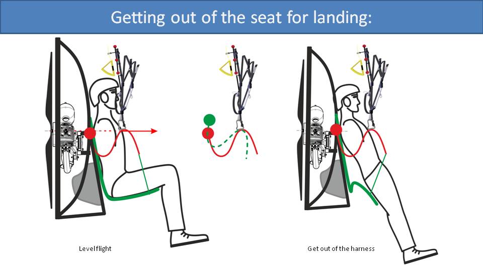
The story changes when you are preparing for landing and need to get out of your seat. You want to be in a standing position, hanging out of the harness, waiting to run upon touchdown. You might think that when you press your legs down and push the seat board down, then the bar will move down like it was before takeoff. But it doesn’t work that way. Remember that all the weight of you and the paramotor is hanging by the carabiners, and you can’t push them down. So, instead of pushing the bars down, you would need to pivot the backs of the bars up relative to the carabiners. That means you would need to lift the weight of the paramotor up to get the bars into that position, which just can’t happen.
As it turns out, when you get out of your seat, the bar hardly moves. Instead, the seat board folds up as much as it can, and you end up in a straight, but reclined position like the picture on the right. This is not an issue, because you’re moving forwards while landing and this is a good position to absorb the speed. So, as you touch down with your feet, you just run it out.
Previously, when we analyzed getting seated after takeoff, we indicated that having the green strap mounted towards the end of the seat board was best. But it’s the opposite for getting out of the seat. If this strap were too far forward, it would be difficult, if not impossible to tilt the seat board forward. So, the further back the green strap is mounted, the easier it is to get out of the seat.
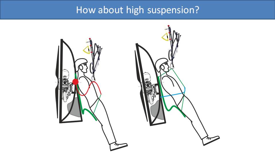
Let’s quickly look at how this works with high-suspension systems. It’s a more difficult situation because the whole suspension is rather rigid, and the bars don’t move at all. So, when you fold the seat board back, you end up in a reclined position, even more so than with gooseneck bars.
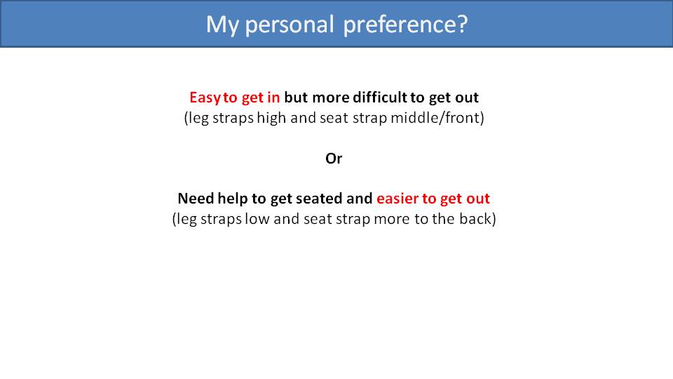
Clearly, we have a situation where there are tradeoffs, the paramotor designer has two options. The first is to put the leg straps high and the seat board strap towards the front. This will make it easier to get seated, but more difficult to get out. The other option is to put the leg straps low and the seat board strap more towards the back of the seat board. This will make it more difficult to get into the harness, but easier to get out. Our preference is the first option, and the reason is for safety. We believe that it’s important to be able to get seated in the harness without the use of your hands and without any distractions. If you reach down to help yourself into your seat and forget to stow your brakes, you could easily stall your glider without any time to recover. Of course, the disadvantage is that it’s more challenging to get out of the seat. But you should have plenty of time to loosen your leg straps if you want and wiggle yourself out of your harness as you prepare to land.
We incorporated some new tricks and techniques into the SCOUT NXT harness that haven’t been seen before. This changes how easy it is to get in and out of it. –Miro
Part 21.2: Getting In and Out of SCOUT NXT Harness
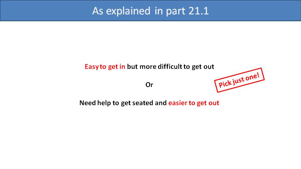
Summarizing where we left off in Part 21, when designing entry and exit from a paramotor harness, there are two primary options. One is easier to get into the seat and harder to get out. The other is the opposite. It’s easy to get out and harder to get in.
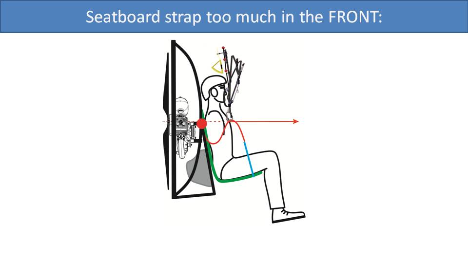
The main issue is the positioning of the strap that connects the gooseneck bar to the seat board. If it’s mounted towards the front of the seat board, your legs will automatically be lifted after takeoff, but it will be difficult to tilt it forward for landing.
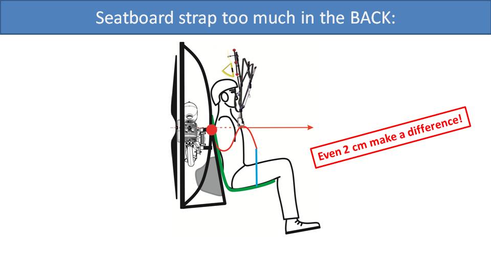
If it’s mounted towards the back of the seat board, you will struggle to get into your seat and may need to reach down and help yourself in. But it will be much easier to tilt the seat board forwards and get out for landing. It comes down to a decision of just a few centimeters and can make a big difference. We were not satisfied with having to make this tradeoff, so we came up with a new solution called the “sliding seat board”.
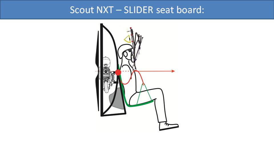
Instead of mounting a single strap somewhere in the middle of the seat board, we mounted a strap from the back of the seat board, up through a pulley, and then down to the front.
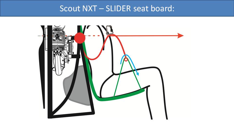
Taking a closer look, the strap that suspends the seat board can slide freely on the pulley. This means that the whole seat board is a lot easier to tilt forwards and backwards. In fact, on takeoff, it tilts all the way back without putting pressure on your legs. However, there is a catch with this design. If you pull some high-G maneuvers, like big wingovers, the seat board will slide all the way up such that your knees get pushed up towards your chin. Of course, this is undesirable, but there is an easy solution.
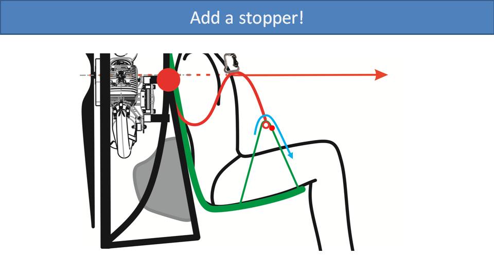
If we add a stopper to the front of the strap near the pulley, then it will prevent the seat board from tilting too far upwards. But when landing, it can still slide all the way forward to allow the seat board to tilt down.
Let’s look at how this works on the SCOUT NXT harness. Starting with the bars up at the in-flight position, the seat board is in a normal seated position. Its straps are looped through the shackles, which act as pulleys. The red straps act as stoppers to keep the seat board from tilting too far upwards, and they’re adjustable on the ground to your preference. For takeoff and landing, the seat board straps slide forward through the shackles and allow the seat board to tuck nicely behind your backside. This is a cool design, but there’s more to the story regarding your landing position.
Landing positions are not completely ideal with typical paramotor designs. The SCOUT NXT’s innovations change the game. –Miro
Part 21.3: Landing position in the SCOUT NXT
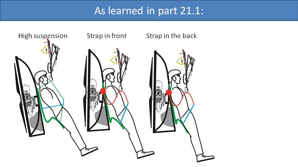
As we discussed in Part 21, landing positions are not perfect on paramotors. On high-suspension systems, the pilot will be the most reclined of any design because the seat board doesn’t have much room or flexibility to move down. On gooseneck bar systems, it depends on where the seat board strap is positioned. If more towards the front, then the seat board is more difficult to tilt forward, and you will end up a little more reclined. If the seat board strap is towards the back, then it will be easier to tilt the seat board forward and your landing position will be less reclined. However, it makes getting into the seat more difficult.
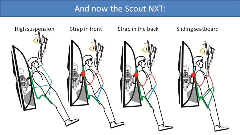
Now we’ve added the SCOUT NXT and it’s sliding seat board. As the straps slide through the pulleys, the seat board easily goes all the way down. It’s easy to press it down with your legs and you can get closer to a vertical landing position than the other designs. But this is not the whole story. Just looking at these pictures, the SCOUT NXT’s landing position looks to be perfect. However, we must consider the flare.
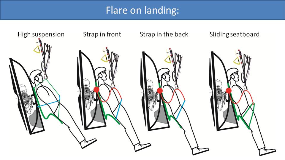
As you flare, you slow the glider down significantly and it swings you and the paramotor forwards. So, we’ve tilted each of the pictures to include the flare just as you’re about to touch down. One good technique to compensate is sliding your feet on the ground to help maintain an upright position, especially with faster gliders. The sliding seat board makes it much easier to get fully out of the harness and prepare for landing. But it’s not magic. You still need to use proper technique.
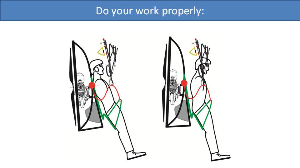
That is, you must lean forward. You must move the mass of your body and your center of gravity as much forward as possible. If you don’t, you will stay reclined and may end up doing a butt landing. So, wiggle forward, and lean forward in between the carabiners as much as possible. The SCOUT NXT makes this even easier because there is no horizontal strap in the front. So, you can lean fully between the carabiners, pull the paramotor with you, and achieve a nice upright position for landing.
Most paramotor harnesses are similar. Yet, there are some that are more comfortable than others. Let’s look at the details. –Miro
Part 22: What Makes a Comfortable Harness
The core of a harness is its straps. The straps may not always be visible if covered by fabric, but they are the skeleton of the harness. They are the key element that gives the harness its strength and security. The routing of straps in paramotor harnesses is derived from paragliding harnesses. Yet, there are significant differences in requirements between paramotor and paragliding harnesses when it comes to their comfort.
The only comfort requirement for paragliding harnesses is flying for many hours at a time. But paramotor harnesses have several more demanding requirements beyond in-flight comfort. First, paramotor harnesses need to be comfortable while on the ground. A pilot may walk hundreds of meters with the paramotor on their back to get to an LZ. Secondly, the harness must be comfortable enough to run with while suspending all the paramotor’s weight. Finally, paramotor pilots love to lean out of the harness and onto the leg straps to do some epic foot dragging.
All these extra requirements don’t pertain to paragliding harnesses. You don’t wear them on the ground for great lengths, and even then, they don’t need to support any extra weight. When launching a paraglider, you just need to take a couple of steps off a hill. And you don’t ever jump out of your harness and hang from the leg straps for foot drags. So, even though the basic harness geometry is the same between paramotors and paragliders, there are notable differences in their needs. Let’s have a look at the details.
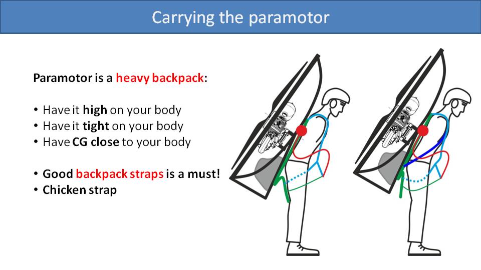
While carrying a paramotor on the ground, it’s not much different than carrying a heavy backpack. Like a heavy backpack, you want to position it high on your body and have it tight. You also want its center of gravity as close to your back as possible. Like we detailed in Part 7, taking care of these details will make the paramotor feel lighter while wearing it.
We have seen paramotor harnesses that just copy the routing of the straps from a paragliding harness and that’s it. We can see this on the left picture. The light blue shoulder strap just goes down and connects to a strap in front of your body. This is connected to the leg straps and then to the seat board. It’s possible to carry a paramotor like this, but it’s quite uncomfortable. With this design, the paramotor slips down your back, which then presses the seat board against the back of your thighs to distribute the weight. This is uncomfortable to walk with, let alone run.
In the picture on the right, we can see a solution to this problem that is commonly incorporated into paramotor harnesses. The dark blue “backpack strap” loops over your shoulders and connects to the bottom of the frame, like a backpack. Because of its direct connection to the frame, it will carry the weight of the frame, the engine, and the fuel tank by this strap on your shoulders. For the most comfortable walking and running, make sure to keep this backpack strap tight and the paramotor high on your back. If it’s loose, the paramotor will sag down your back and will be less comfortable to walk with.
There also may be a “chicken strap”, which is a small strap that connects the shoulder straps together. Connect and tighten this strap so the shoulder straps don’t slide around, which will make sure the load is distributed evenly.
There is another advantage of adding the backpack straps. With the backpack straps tight and holding the load of the paramotor on your shoulders, the rest of the straps can remain loose. So, the suspension bars can move freely, which means the seat board straps will be loose and the seat board won’t press up against your legs. The leg straps can also be loosened for good leg movement.
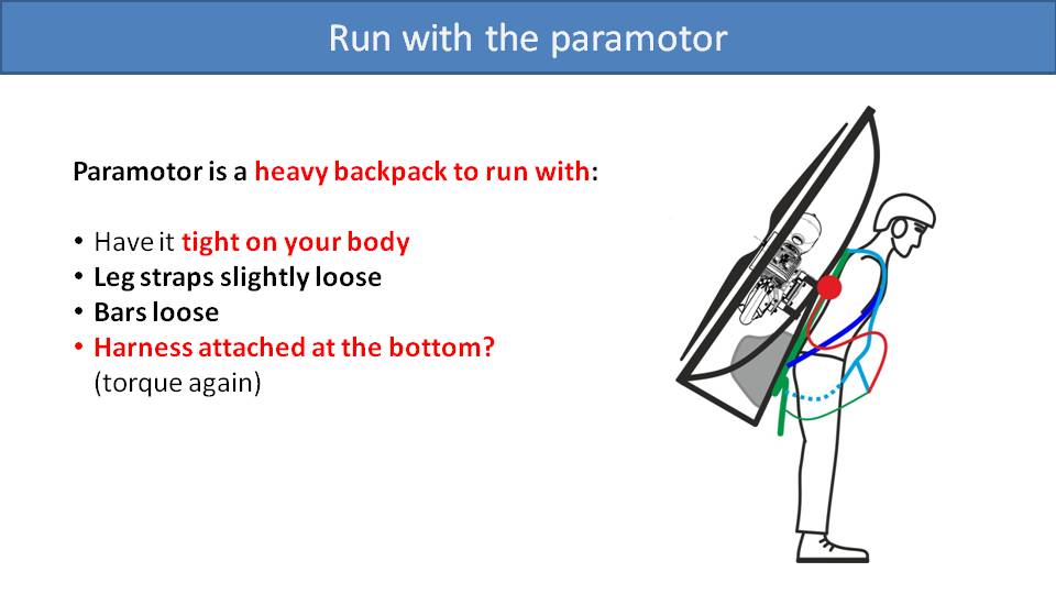
So, while running with a paramotor on your back, the backpack strap is essential. Make sure it’s high and tight on your body. Loosen the leg straps just enough so you have full freedom of movement. Make sure the bars are loose until the glider starts lifting them. Another important design choice that helps running with the paramotor is that the harness is attached at the bottom to the frame. Otherwise, as you’re running and adding full throttle, the torque will twist the paramotor away from your body. But with the backpack straps connected to the bottom of the frame, it will hold the paramotor in position against your back.
When hanging from the harness, it’s important for gentlemen pilots that the leg straps are wide and pulled towards the outside so that the pilot’s weight is all on their thighs and not on other sensitive areas. Beyond this, we covered the other details of comfort while hanging in the harness in Part 21.
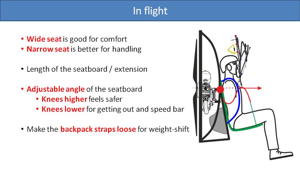
Most paramotor harnesses are comfortable in-flight. But we can analyze some aspects that make some harnesses more comfortable than others. A wide harness with room to move around will be more comfortable. On the other hand, a snug harness will give you better feedback from the glider and better weight-shift. The length of the seat board is crucial to in-flight comfort. If the seat board is short, it will give you a feeling of falling out and your weight will be distributed over a small portion of your legs. After a while, this can get uncomfortable. But, if the seat board is too long, it will press up against the backs of your knees and quickly get uncomfortable.
A seat board with an adjustable angle can be nice. You can adjust it higher to tuck you into the seat and give you a feeling of security. Or you can lower it some for more freedom of movement for your legs. This will make it easier to use the speed bar, get out of your harness for foot drags, or for landing. Some paramotors designs might have the front edge of the seat board adjustable for this purpose, too.
We talked earlier about tightening the backpack straps while carrying the paramotor on the ground. But once you’re in the air, there is no need for these straps to be tight. So, you can loosen these straps to be more comfortable and to give you more room to move around and weight-shift.
Paramotors are sometimes referred to as backpack aircraft. While it’s true that they are amazing aircraft, they are bad backpacks. However, things have changed with the SCOUT NXT. –Miro
Part 22.2: Carrying a Paramotor with a Waist Strap

In this picture from Part 22, we concluded that to make paramotors more comfortable on the ground, you need them to sit as high and tight as possible on your back. So, by including a simple backpack strap that goes from the top of the frame, around your shoulders, and down to the bottom of the frame, ground handling and running was greatly improved. But trekking backpacks have some more tricks that we might be able to leverage. Let’s look at their geometry.
Here is a standard trekking backpack that every mountaineer and serious hiker is familiar with. Notice that the shoulder straps are not attached to the top of the backpack, but instead a little lower. This means the load can ride higher on your back. A small adjustable strap is added at the top to keep it stable. Then, there is a strong waist belt to take the weight. Let’s see how we can apply this to a paramotor harness.
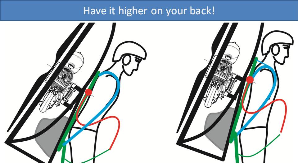
On the left is a standard design. The backpack strap goes from the bottom of the frame, up over the pilot’s shoulder and attaches to the top of the frame. So, the weight of the paramotor will pull the top of the frame down below the pilot’s shoulders. On the right is the SCOUT NXT’s design, where we have attached the backpack straps to the frame much lower. Now, the top of the frame sits above the pilot’s shoulders. Then, we added a little adjustable top strap like the backpack to keep the frame close and tight. We can see in the picture that the weight of the paramotor now sits much higher on the pilot’s body.
This has notable benefits. With the paramotor higher on your back, you have more ground clearance and more leg room. So, you can take large strides while quickly running for takeoff. Also, with the weight of the paramotor higher on your back, it feels lighter. This is because you need to lean forward less to keep your balance.
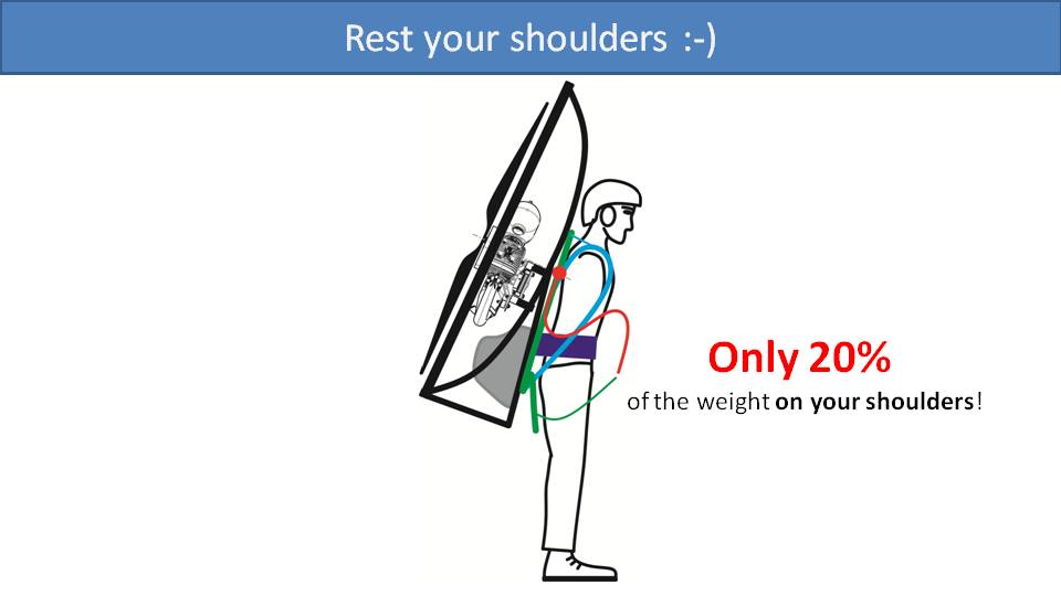
The other inspiration from trekking backpack designs is a waist belt. Mountaineers and hikers know that tightening their waist strap can transfer most of the weight of the backpack onto their waists and off their shoulders. We have incorporated this onto the SCOUT NXT and it works like magic.
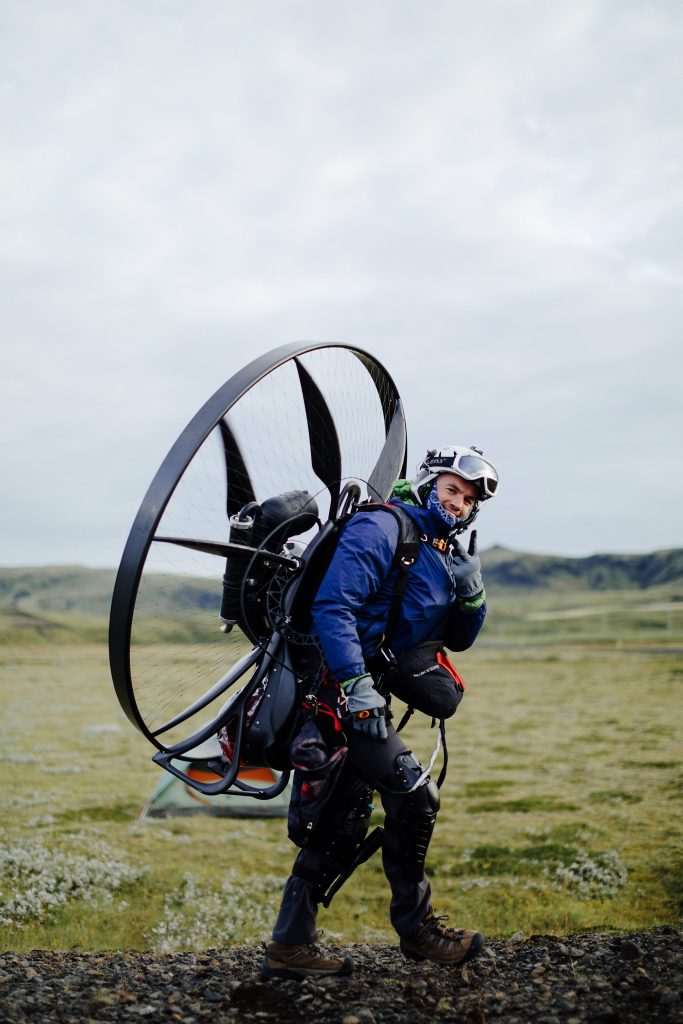
You can see here that the shoulder straps are completely loose and nearly all the weight of the paramotor sits on the waist strap. This makes the paramotor feel lighter than it actually is, and you have full mobility in your shoulders. However, we recommend that you tighten the shoulder straps a little to take about 20% of the weight. This will give you better feedback from the motor and the glider. With this setup, ground handling and glider control are much easier while taking off. So, it seems that incorporating backpack features into the paramotor harness has great benefits. But there is a catch. As with most design choices in the paramotor world, there is a tradeoff.
If the thrust line is at the standard height relative to the pilot, it pushes forward near their center of gravity and they just go forward.
If the thrust line is higher on the pilot’s back and you abruptly apply a lot of power, it will try to flip them down to the ground. So, while having the paramotor high on your back gives you advantages like more legroom, more ground clearance, and more room for giant running strides, you need to be careful going to full throttle. You must be patient and gradually go from idle up to max power as you gain speed. This is beneficial for good glider control anyway, and if done correctly, there is no issue. If not done right, you will be punished with a face plant.
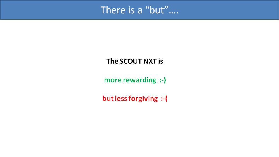
So, the harness design on the SCOUT NXT is more rewarding and more pleasant on the ground if done right, but less forgiving if not. As such, it is probably not ideal for novice pilots.
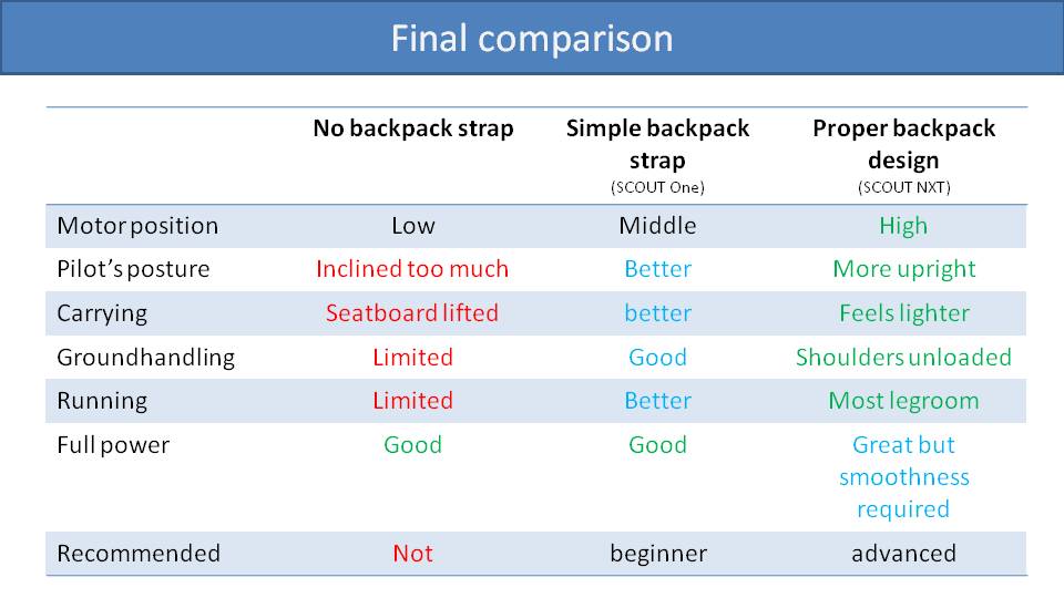
Here is our final comparison of harness designs for carrying paramotors on the ground. On the left, we have harnesses with no backpack straps. Basically, the shoulder strap is attached to the seat board. The motor will droop down your back, requiring you to lean forward. The seat board will be under tension and press against your legs. It won’t be comfortable and will make ground handling and running during takeoff more cumbersome.
Then, if we add a simple backpack strap, as in the SCOUT One and many other paramotors, it greatly improves the situation. Your posture will be better, which will make for easier ground handling and running on takeoff. When going to full throttle, it will push you in the middle of your back in a natural way. So, this is what we recommend for beginners.
Finally, with a proper backpack design as included on the NXT, the motor is much higher on your back. This means you will stand more upright, and it will feel much lighter with most of the weight being on your waist. With your shoulders unloaded, you will have better ground handling and feel for the glider. And you’ll have more leg room for running on takeoff. It’s a great solution if you are sure to gradually increase throttle on takeoff. So, we recommend this design for more advanced pilots.
In most countries, no load testing or certification is required for paramotors. So, you might not have any idea if your flying machine is safe enough for you. But there is a way to test and certify a paramotor design. –Miro
Part 23: Load Testing and Certification
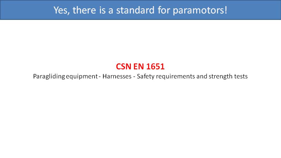
Even though most countries don’t require testing and certification for paramotors, there is an official standard that can be used. The European Norm EN-1651 standard illustrates safety requirements and strength tests for paragliding harnesses. We can apply EN-1651 to paramotors as well. The foundation of this standard is the load test, and the concept is simple. You put a test dummy into the harness and fasten the straps in a conventional manner. Then, you suspend the carabiners of the harness by the testing system. Its hydraulic ram is then connected to the hips of the dummy to apply load to the harness. When you push the red button, the hydraulic ram increases the load into the harness to simulate the high-G scenario you want to test. There are a few authorized laboratories who can perform these tests.
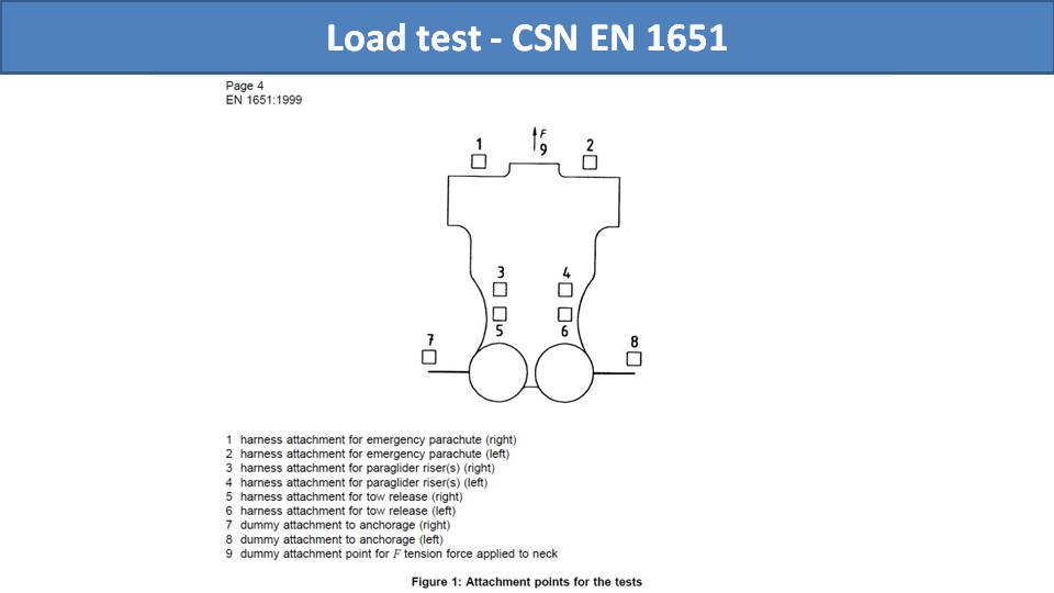
With this hydraulic test system, there are a variety of tests to perform, all at high Gs. The first test is in a normal flying position. The dummy is put in a typical seated position for two tests. One is at a load of 9 G for 10 seconds, and then the other is at 15 G for 5 seconds. Then, these tests are performed again with the dummy out of the seat, as if it were preparing to land.
The last is a crazy test with the only one carabiner attached. As the load increases in the paramotor, it banks and pushes all the way to the side. It is a bit scary and impressive to watch.
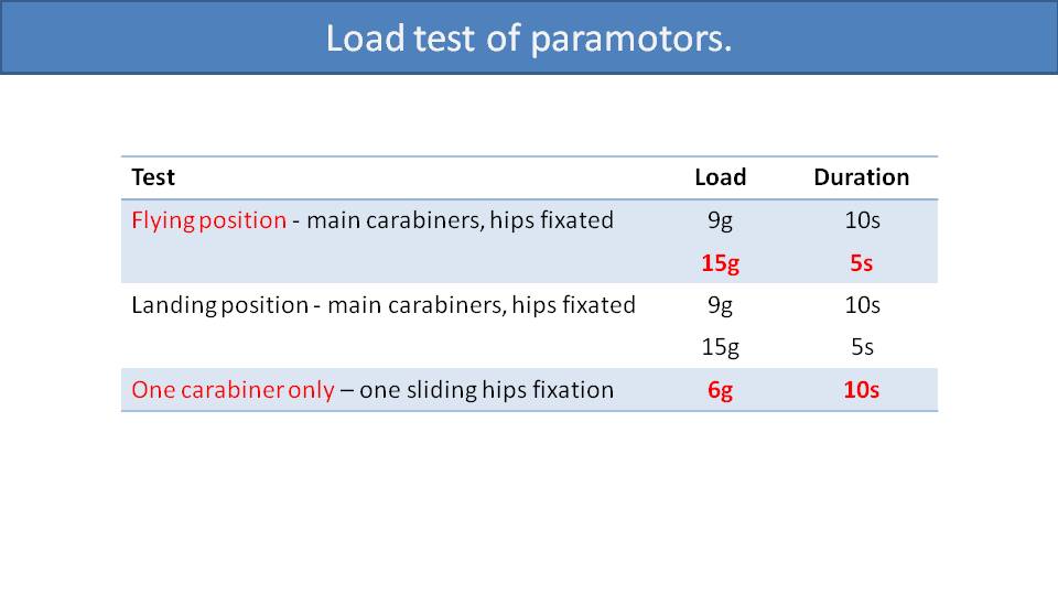
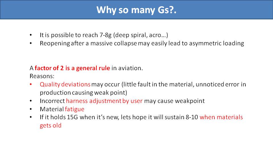
You might be wondering why the paramotor is tested at such high Gs. No one would be able to survive 15 G. But you might pull 7 or 8 G in a tight spiral or a dynamic acro maneuver. You also may asymmetrically load one carabiner while recovering from a massive collapse. After the collapse, you could fall for a bit and then impart a large shock force on the paramotor as the glider reinflates and catches you.
The typical standard in aviation is to test for twice the load that you expect to encounter. Since we would expect the maximum load for paramotor pilots to ever encounter is 7 or 8 G, that gives us a 15 G test case. There are a few reasons for testing with such a large safety margin. The first is to account for the possibility of a defect in manufacturing. So, if there was a subpar weld or harness stitch, it should still survive. Second, is to account for fatigue in the materials over time. Finally, is to account for pilot mistakes. Perhaps they didn’t connect and adjust their straps properly, or they overloaded the harness.
The idea is, if a perfect paramotor can survive 15 G when it’s new, then one with a sketchy weld should survive 8 or 9 Gs when it’s old. We maintain and repair paramotors for years and years and expect them to take care of us. So, testing at 15 G is not an exaggeration in that regard.
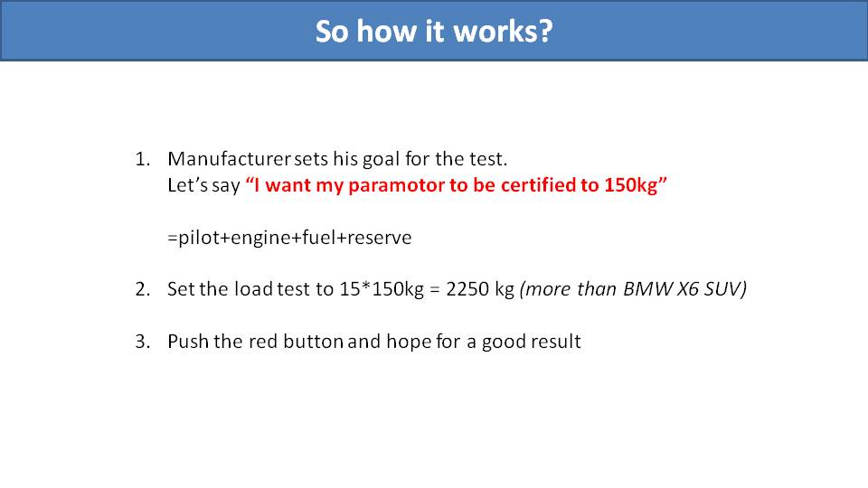
The way that the testing works is that you bring a frame and harness to the laboratory to be tested together. You calculate the maximum weight that you want your harness to be certified for. This weight would include the harness, the motor, the fuel, the pilot, and anything else on the paramotor. To test for 15 G, you just multiply that weight times 15 to get the force to be applied by the hydraulic system. For example, if we assume a SCOUT with a full fuel tank and some gear weighs 35 kg and then add a 115 kg (250 lb.) pilot, that would be an all-up weight of 150 kg. Multiplying this by 15 is 2250 kg. So, to simulate 15 G, the hydraulic press pushes the dummy until the weight at the carabiners measures 2250 kg.
Before the test, every structural component of the harness is marked. The fabric is not critical, so it’s not marked. Rather, the straps within the harness, the carabiners, every buckle, and every slider are all marked with a white marker. Then you push the red button and hope for the best. No strap or bar can break. No stitching can detach, not even a single stitch. No buckles or sliders can move from their original position and no other deformations are allowed. In other words, to pass the test, the harness must appear as it was before the test. The only thing allowed to break is the seat board, and hearing it snap and crackle during the test is certainly unnerving. The test is either a success or failure, with nothing in between.

We must clarify that EN-1651 is not a rule, but a standard. Each country has a choice to adopt this standard (or any other standard) as a rule for certification. Some countries require passing EN-1651 to be certified. Some also add requirements such as noise tests or wiring inspections, too.
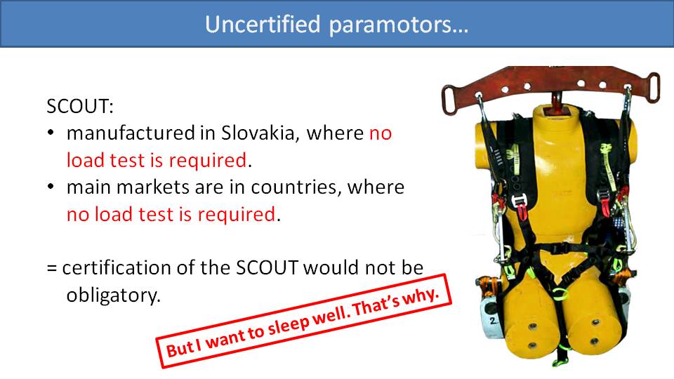
But the vast majority of countries have no load test or other requirements for paramotors, and you may end up flying a completely untested and uncertified paramotor. And it will be completely legal to do so. This holds true for the SCOUT. It’s manufactured in Slovakia where such testing is not required, and it’s mostly sold in countries where no testing or certification is required. However, we have performed and passed EN-1651 at a total all-up weight of 150 kg (330 lb.) for one simple reason. Your safety is important to us. Otherwise, we couldn’t sleep well at night.
I personally know two pilots whose suspension bars on their paramotors broke in-flight. Luckily, they are both alive, but this type of failure can have serious consequences. –Miro
Part 24: Suspension System Strength
The strength and integrity of suspension bars are critical to the safety of a paramotor. This is especially true with the bars’ attachments to the frame, as they are the weak points for most paramotors. There are four factors to look at when examining the strength of a paramotor suspension bar:
· The material the bar is made of
· The size, shape, and construction method of the bar
· The design of the bar’s attachment to the frame
· The strength of the attachment bolts themselves
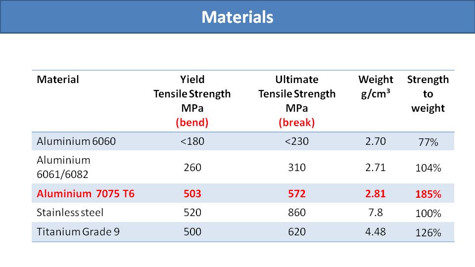
Here is a table of materials that are commonly used for manufacturing paramotor suspension bars. The first two columns show the threshold at which each material will bend and then break. If a weaker material is used, then you simply need to use more of that material to achieve the desired strength. In this table, we can see that 7075 T6 aluminum has the best strength to weight ratio. However, for a given size, stainless steel and titanium are a bit stronger. Because of its fantastic strength to weight ratio, we chose 7075 T6 aluminum for the SCOUT’s bars. The downside is that it cannot be welded.

There are two basic construction methods for building paramotor suspension bars. The first is bending and welding, and the second is CNC machining. Bending and welding bars has an obvious advantage. It’s cheap and easy to make in a simple workshop. But the disadvantage is that you are limited to a tube profile.
Creating CNC machined bars is more expensive. There is also more work to design and engineer the shape that will have the desired strength characteristics. Then a CAD model must be created, and the part must be machined. The benefit is that you will have a part whose shape is optimized for that purpose and doesn’t waste any material. In this case, because the bar is loaded from the top, it can be designed with a narrow tall profile that is strongest in that direction. You also will have a wider choice of materials, including the 7075 T6 aluminum.
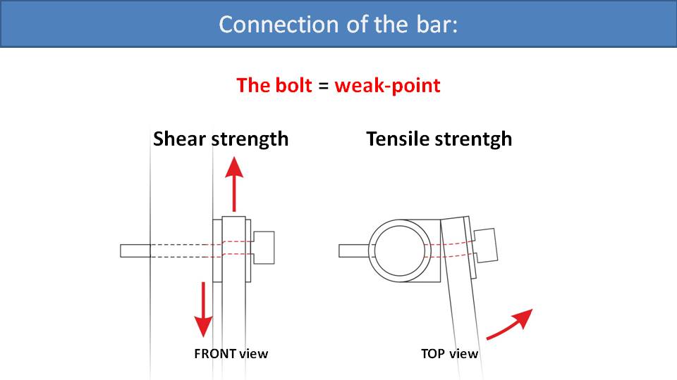
Most paramotors simply bolt the suspension bar to the main frame, and this its weakest point. On paramotors, there are two ways that this bolt is loaded. The first is the shear load. This is the vertical force pulling straight down on the bolt. In the picture on the left, the frame is on the left and the bolt attaches the suspension bar on the right. When you perform a high-G maneuver, your weight in the harness pulls the frame down at this point. This immense force will try to shear the bolt like a big pair of scissors. So, the bolt must have sufficient shear strength to resist this.
The other requirement for this bolt is its tensile strength. In the picture on the right, we are looking at the suspension bar’s attachment to the frame from the top. When the bar is loaded towards the side, it will apply a prying force that pulls the bolt away from the frame. Because the glider spans a large distance horizontally, the risers are always pulling outward on the suspension bars in this manner. But the suspension bars can be loaded sideways even more in other situations. This includes heavy weight shifting, big wingovers, SATs, spirals, or even a recovery after an asymmetric collapse. This is why the sideways load is also tested in the EN-1651 standard.
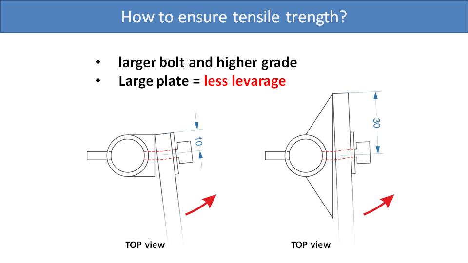
There are two ways a paramotor designer can address issues with tensile strength of this bolt. The first is to upgrade the bolt itself, perhaps using a thicker bolt or a higher-grade bolt. The second option is to use a larger contact plate between the suspension bar and the frame. With a larger contact plate, the sideways force of the bar will have less leverage to pull at the bolt. In the picture on the right, this contact plate is small. So, the bar’s prying force has a lot of leverage and the bolt must have a lot of tensile strength to resist it. In the picture on the right, the plate is like a shoulder that the bar is resting against. So, when the bar is pulled to the side, its prying force has much less leverage when pulling the bolt. In these examples, where the contact plate is three times larger in the design on the right, that means its bolt will experience three times less pulling force than the design on the left. In Miro’s example, his first friend whose bolt broke in-flight noted it was because this contact plate was small, like the design on the left. In fact, he broke this 10mm bolt on two occasions.

When it comes to the shear force that the bolt must resist, the larger contact plate doesn’t help. In Miro’s second example, his friend’s bolt broke from the shearing force and the large contact plate didn’t help. The truth is, a 6mm or 8mm bolt is strong enough to withstand high-G maneuvers on a paramotor, but that’s only the case if it’s new. Over time, the bolt is the subject of fatigue and abrasion and becomes weaker. As the bar rotates about the bolt, it slowly wears it down and reduces its strength. The solution we used on the SCOUT is to not have the suspension bar swivel on the bolt. Instead, it swivels on a massive pin on the frame itself. There is a much larger hole on the SCOUTS bar which slides over the pin on the frame. Then the bolt is attached just to hold the whole system together and does not bear any of the shear load.
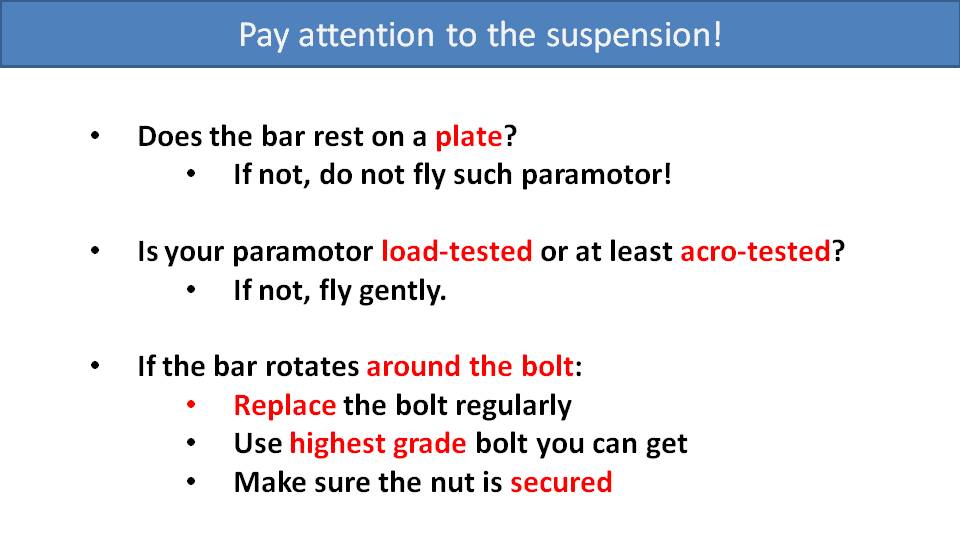
Instead of a summary of design choices, we would like to appeal to all paramotor pilots. For your own safety, please check your suspension. If the bar does not rest on a large contact plate, we don’t recommend flying it.
If your paramotor has not been load tested or at least acro-tested, don’t be a test pilot for the manufacturer. Let someone else do it. If you see some doing repeated and heavy acrobatic maneuvers with that paramotor design, that’s a good indication it will be strong enough for you.
Finally, if the bar rotates on the bolt, and not on a pin like the SCOUT’s, please inspect and replace your bolts regularly. Use the highest-grade bolts you can find and make sure that they are torqued and secured correctly.
We need to talk about crashes. We have some first-hand accounts for you and will show what your paramotor can do to help you walk away from a crash. –Miro
Part 25: Crashes
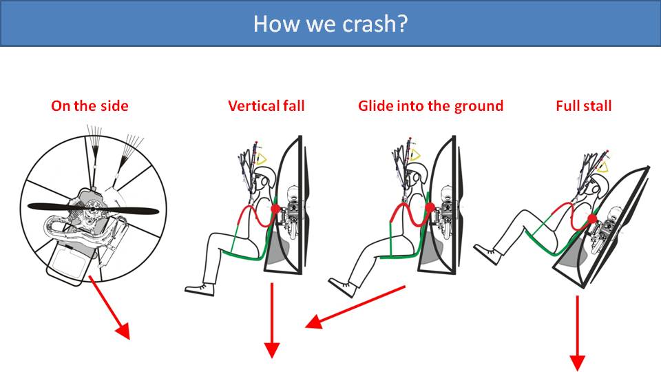
There are four main ways that you might crash. We will go through each of these, including some first-hand accounts. The first is falling to the side. Then, a vertical fall. Probably, the most common crash is gliding into the ground. And finally falling on your back from a full stall.
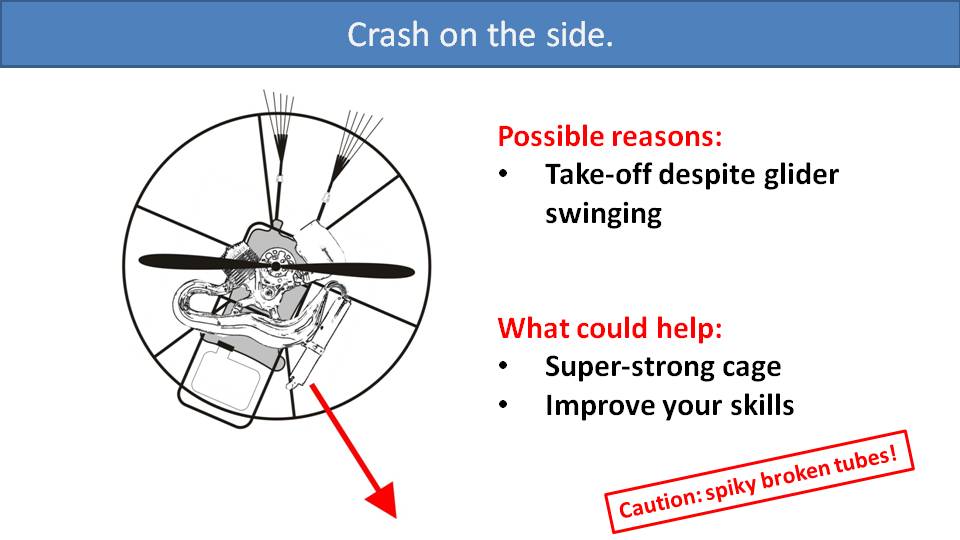
Crashing sideways is typically from beginner mistakes. It can happen if you try to launch while the glider is oscillating. You lift off the ground at the top of the oscillation, think you’re airborne, and then swing back into the ground. Miro had a crash like this when he was a new pilot. This paramotor had an aluminum frame, and one of the broken tubes tore through his jacket and came out the other side. He was lucky that day and didn’t end up with a single scratch. Our friend Matt crashed on his side during a bad landing.
I was still a new pilot and went for a nice flight over the beach. But the winds suddenly picked up and I hurried to come in to land back at the field. The winds were switching direction a lot and I failed to land into the wind. Instead, I landed in a 15kph crosswind and my glider pulled me over to my side as soon as my foot touched the ground. Unfortunately, the glider stayed inflated and pulled me across the field and over a paved pathway before I could disable it. I ended up bending the stand and breaking a few carbon parts on my new SCOUT while taking some scrapes and bruises. I repaired the SCOUT without much issue and learned an important lesson that day. –Matt
The paramotor designer could help by building a strong cage so you don’t have to replace or repair parts. But super strong cages are also much heavier, which makes ground handling more difficult. So, the best course of action is improving your skills to avoid these mistakes in the first place.
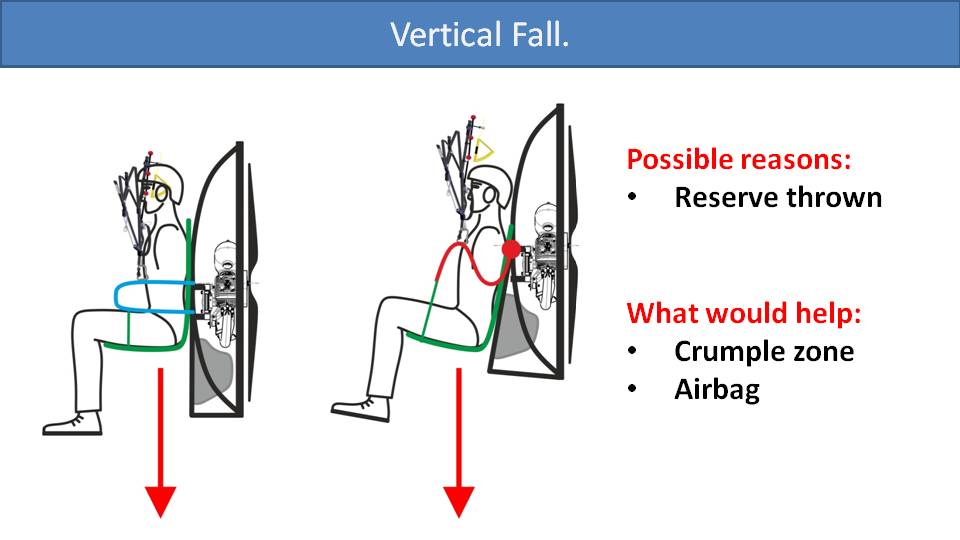
The next type of crash is from a vertical fall. Primarily you might get into this situation when descending under a reserve. Our friend Byron recalled this incident when he had to throw his reserve parachute and he came crashing down vertically.
Yes, I do have a little experience with this type of crash. I feel that my paramotor’s crumple zone was a real benefit to me in this situation. But I also think that there is a misinterpretation that the crumple zone is an all-encompassing protection zone, which it isn’t. It only helps if you fall vertically. I ended up with three broken ribs, a compression fracture, and a hematoma that went down the back of my leg that lasted over a year. You don’t walk away from a crash like that, you limp away. But there is more to this story. The reason I crashed so hard is because I threw my reserve but didn’t disable and pull in my glider. Then, they down-planed. When this happens, the glider and the reserve parachute spread away from each other and both end up flying parallel to each other on opposite sides of you pointed towards the ground. You then keep accelerating until you hit terminal velocity. Thankfully, I didn’t have enough time to get going that fast. But everything hit the ground at the same time with amazing speed just because I didn’t disable my glider. I didn’t have the training to handle that situation, and that’s why those injuries happen. –Byron
Reserve parachutes are designed for a slow descent, so you can land without any major injuries. You should be able to walk away from this type of crash, with or without a crumple zone. But, if you come down on a reserve faster than expected, a crumple zone can help. The better solution for these types of accidents is an airbag. Some paramotor manufacturers include an airbag under the seat. But it’s not common, because it creates a lot of drag in-flight and can be annoying to deal with. The best solution is to fly with a properly sized reserve parachute and be well-trained on how to throw your reserve and disable your main glider.
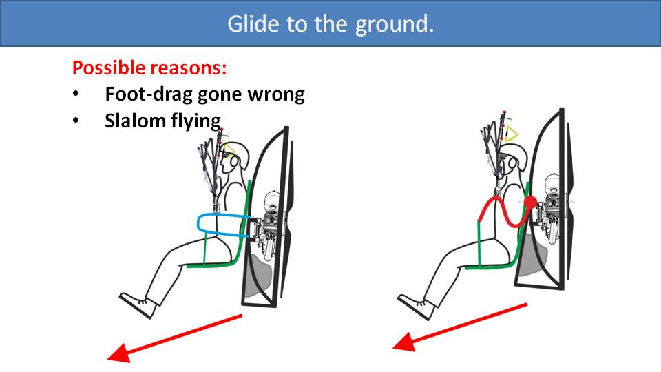
There is a much greater chance that you will crash into the ground while gliding. So, your descent rate will be slow, but you’ll have a fair amount of forward speed. There are a few scenarios where this can happen. It can be a failed landing, a failed foot drag attempt, or a mistake while slalom flying near the ground. In this type of crash, a crumple zone won’t help at all. In fact, it’s a disadvantage.
The paramotor on the left has a larger crumple zone and the paramotor on the right has a smaller one. If you hit the ground with a lot of forward momentum, the crumple zone will hit the ground first, dig into the ground, and pivot you forwards.
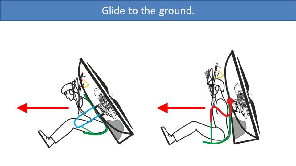
The picture on the left shows how this will fold you forwards and throw your head towards your knees with risk of serious injury. The paramotor on the right has no crumple zone. So, your butt will hit the ground and slide along with the cage. You may hit harder than you’d like, though. In this case, an under-seat reserve helps as it acts as a cushion. But at least you will slide and not come to an immediate stop as you might with the paramotor on the left. Most paramotors round off the leading edge of the paramotor frame at the bottom to make sure the paramotor slides in these situations.
I witnessed an accident just like this. I had loaned my paramotor and my 18m Snake to a friend of mine. He was flying really fast with full speed bar, and fully trimmed out while close to the ground. He failed to control the glider and hit the ground at full speed like the picture on the right. He ended up completely rolling twice before coming to a stop. The cage was completely destroyed which was good for him. While rolling and destroying the cage, this allowed him to dissipate all that energy over a large distance. So, he wasn’t exposed to a sudden deceleration and walked away from that crash. The paramotor didn’t fare so well, but it’s an easy trade for your livelihood. –Miro
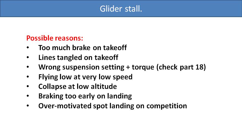
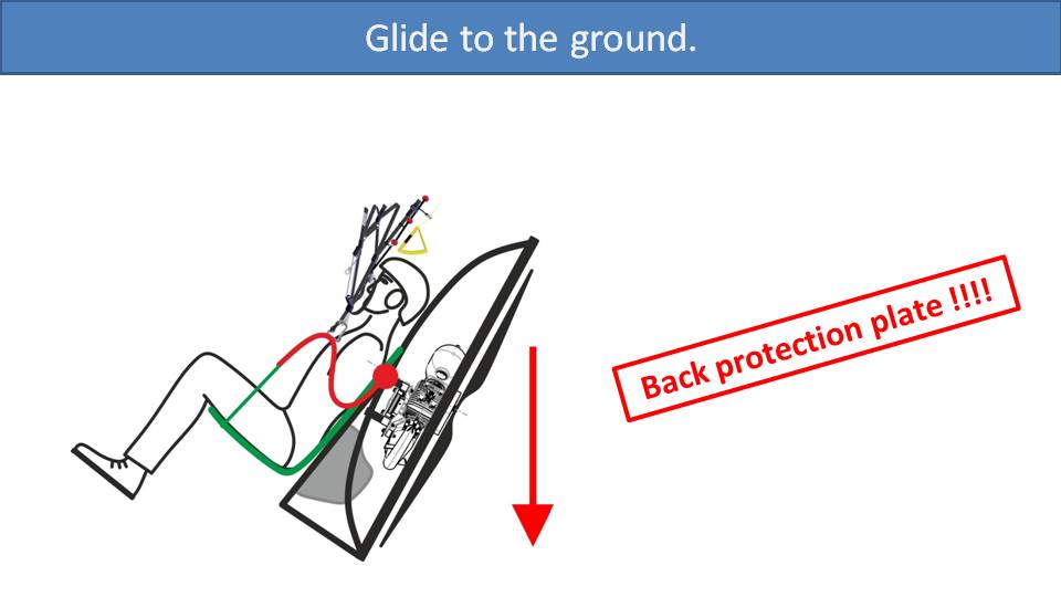
The third common type of crash on a paramotor is due to a glider stall. This can happen for a few reasons. Usually, it is from too much brake input while launching. This is what happened to Miro once with the aid of some tangled lines.
Several years ago, I took off from a dirty industrial area with a lot of brush. Some of that brush got tangled in my lines and I didn’t notice it. Right after I took off and released my brakes, I started turning to the left. Little twigs had caused my lines to tangle with my left brake line. I tried to pull right brake to compensate. But my speed was too low as I was trying to climb at full power to avoid a building on the left. I ended up stalling my glider and fell straight down. –Miro
There are some other reasons that a glider might stall. One is due to incorrect suspension settings and torque twist, as we discussed in Part 18. Or, a glider can stall at very slow speeds, which might happen in a minimum/maximum flying speed competition at an event. If a glider takes a collapse at low altitude and doesn’t have a chance to reinflate, this also will result in a crash under a stall. Another common beginner mistake is fearing the ground on landing and flaring too early. If they finish their flare too high, they will fall to the ground in a stall position. The last situation that we see in competition is over-motivated spot landings. The pilot tries too hard to hit the spot landing and stalls the glider.
There is one more type of accident that could cause you to fall on your back, and that is hitting a power line. You will swing forward before falling to the ground on your back. In this case, the most important safety feature of your paramotor will be its back plate. For some reason, many paramotors don’t have a back plate. There is just a simple tubular frame between your back and all the engine parts. Please, if your paramotor doesn’t have a back plate, make one out of plywood or whatever else you can to distribute any impact to the largest surface possible. In Miro’s accident when the brush was tangled in his lines, he fell completely on his back. Thankfully, the SCOUT has an ergonomically shaped carbon fiber backplate that saved him.
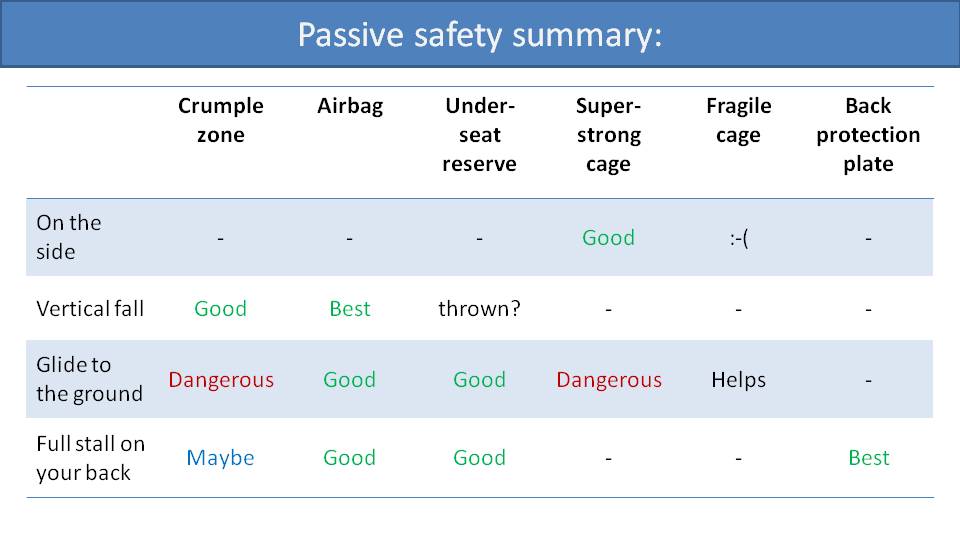
In summary, we have our four crash scenarios versus the passive safety features. The crumple zone will help you in a vertical fall, which happens when you throw a reserve. Otherwise, it’s of little help and can be dangerous if gliding into the ground. If you hit the ground under speed, the crumple zone will prevent you from sliding and will fold you forwards.
An under-seat airbag is a good solution, but very few brands include it. This is because it’s a hassle and creates a lot of drag.
An under-seat reserve doesn’t help when falling to the side. It won’t help on a vertical fall, because presumably you’ve thrown it. But, in other types of crashes it can be a cushion that dampens impact between your butt and the ground.
A super strong cage can save you money as you won’t need to repair it often and it will protect the propeller, especially on sideways crashes. But, if you glide into the ground under high speed, it will prevent you from rolling to dissipate speed. A fragile cage, on the other hand, might help you walk away from such an accident.
We believe a back plate is a must, so please find a way to add one to your paramotor if it doesn’t already have one.
If you crash because of a stall, you need to maximize your protection to reduce your chances of injury. — Miro
Part 25.2: Improvements in Protection from Stall Crashes

In part 25, we covered various types of crashes depending on the angle of impact. However, we’d like to go into greater detail with the full stall scenario when you fall on your back.
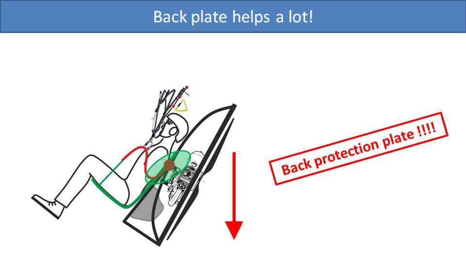
We had discussed that if you fall on your back like this, you don’t want the tubes of the paramotor frame cutting into your back and causing damage. Instead, you want to distribute the impact across a large area of your back. The way to do this is to install a backplate. Let’s look at backplates.
This is a backplate for motorcycling that we can learn from. It has a hard shell of solid material for back protection. We have met pilots who said they were satisfied with the foam backing in their harness. But two centimeters of foam won’t be able to slow you down nearly enough to prevent injury. It will not be able to distribute the impact to a larger surface, and they are not a suitable crumple zone. Crumple zones are designed to absorb impact over a large distance, and two centimeters is not nearly enough. A proper crumple zone might need to be up to a meter to help.
On falls like this, there is no way to build in a crumple zone. The frame and the fuel tank will help some, but you don’t want foam on your back. You want a plate. It can be plywood, plastic, or carbon fiber, but it must be a solid plate. If we look further, backplates are usually behind your upper back, but that’s not the only part of your body exposed to injury.
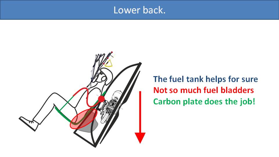
A typical backplate protects the upper back and not the lower back. Most paramotors usually solve this by installing the fuel tank right against the back which acts as another backplate. Many designs have the frame tubes on either side of the tank. But, if the frame tubes are between the pilot and the fuel tank, it is best to design the tank such that these tubes are embedded in the tank to provide that smooth solid backplate. Paramotors with fuel bladders instead of tanks do not solve this issue.
But the best solution is to extend a carbon fiber backplate all the way down to make sure that any impact is completely and evenly distributed across your whole back. This is what we have introduced with the new SCOUT NXT. Instead of having a carbon fiber plate on the upper back only, we have it for the lower back as well in a nice ergonomic shape for the best comfort and protection.
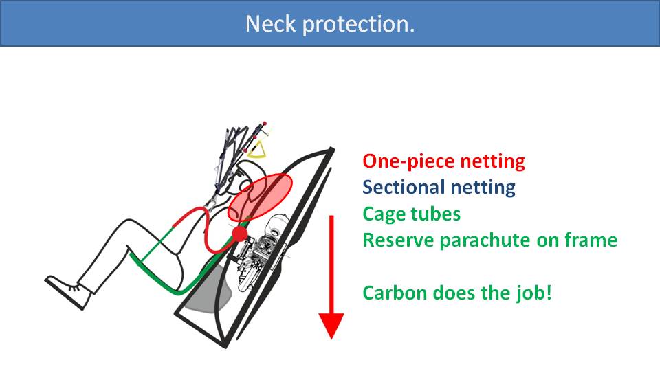
If falling on your back, obviously your head will be thrown back and you could break your neck if you have a large impact. If there is one-piece netting, like the SCOUT One and many other paramotors use, it may not help enough. It just flexes too much. Sectional netting, like on a Flat Top and some other frames, will be slightly better since the smaller sections flex less. Cage tubes behind your head are a good solution. The idea is to have a metal loop or some solid material behind your head. Then your helmet will hit it and stop your head from flinging backwards. Some paramotors position the reserve parachute on a structural part of the frame behind your head, which is a great solution. The parachute will act as an extra cushion for your head.
We didn’t address this issue as well as we would have liked on the SCOUT One. We wanted to improve this on the SCOUT NXT, so we added a carbon fiber extension at the top of the frame.
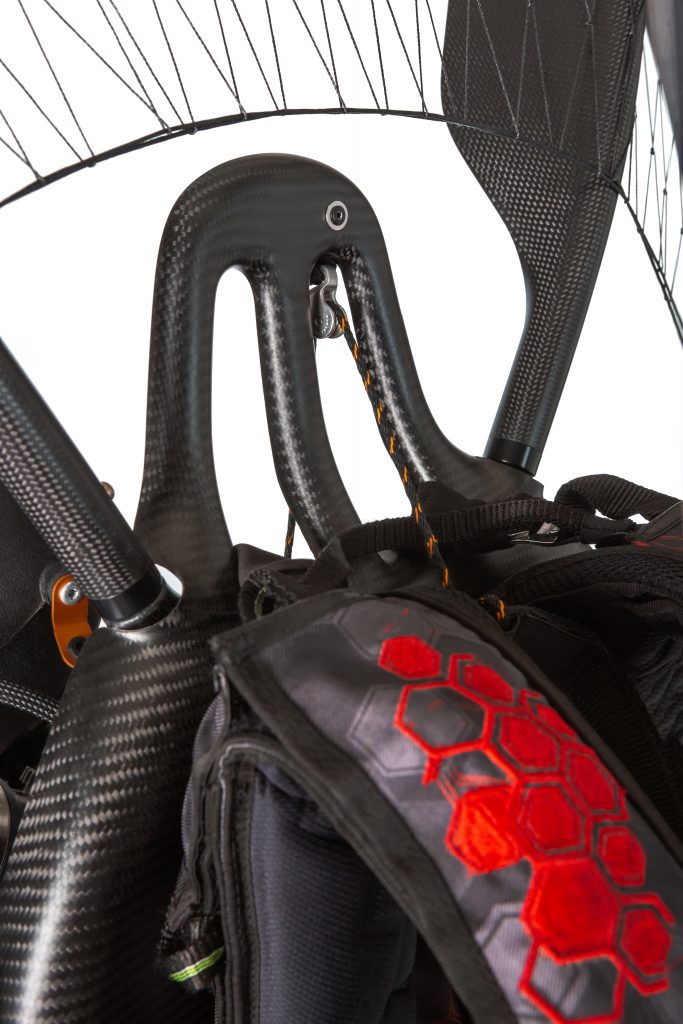
It looks awesome, reminiscent of a race car headrest, and provides your neck much more support in case of a bad crash.
If your throttle cable goes into the propeller during flight, the best you can hope for is an emergency landing. The paramotor designer is probably to blame for this accident. –Miro
Part 26: Throttle Cable Safety
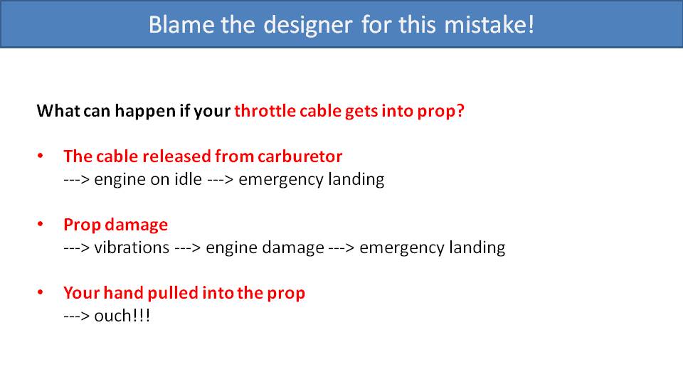
If your throttle cable goes into your propeller, hopefully the cable will detach from the carburetor. Then the motor will continue to idle, and you will glide down and hope for a good emergency landing spot. One of our friends was not so lucky when this happened to him while we were doing some bivouac flying all around Slovakia. As he was braking heavily, the slack in his cable looped through a gap in his frame back into his propeller. His propeller was damaged, and his engine started vibrating horribly. That could cause serious damage, so his journey was cut short.
The worst-case scenario is if your hand, strapped into the throttle, is pulled backwards into the propeller. That will probably result in a serious injury.
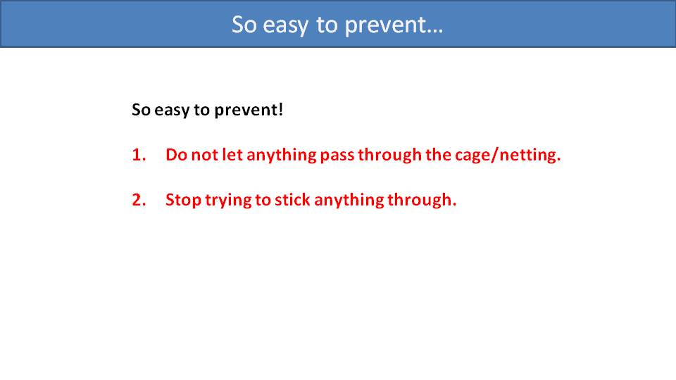
It’s easy to prevent these types of accidents. The first way to prevent them is in the design of the cage and netting. They should be designed in a way to minimize the gaps where the throttle cable can get through.
As a pilot, make sure to grab your throttle such that your cable goes over your shoulder and not under your armpit. Then, be aware of your cable while in-flight, and its propensity to loop back through the cage and try not to do it.
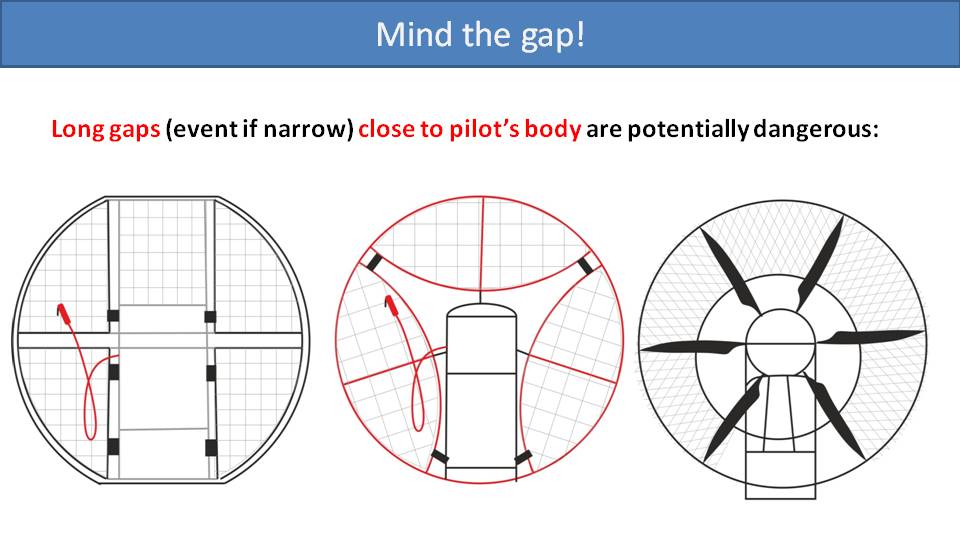
Mind the gaps, especially any long narrow ones that will make it easy for a loop to slip through. Every paramotor on the market has some gaps. The two paramotors on the left have gaps between the cage sections. In these cases, try to position the Velcro straps to minimize the gaps. You could even add a few more of your own. Many paramotors are similar to the one on the right, but there are still gaps to pay attention to.
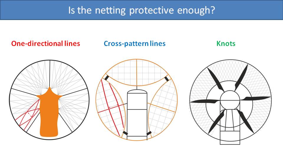
The next thing to consider is the pattern of the netting. The least protection is provided by netting that goes in one direction to the hoop in a pattern like bicycle spokes. This type of netting can easily slide and create large gaps for a throttle cable to go through. Netting lines that are designed in a cross pattern provide more protection, but they can still slide and create larger gaps. The best protection is with netting that is knotted. The mesh can’t slide and spread, so the gaps will always remain about the same size.
These are important considerations, but the most important is the position of the throttle cable.
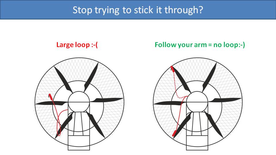
If the throttle cable is attached to the frame at the bottom, then it must be quite long to ensure you can still reach up for your risers. But when you pull your brakes low, a large loop in the cable will be created which may go back into the propeller. The better solution is to mount the throttle cable up by your shoulder and make sure it’s just long enough to allow you to reach up. In this case, an arm-length cable will just track with your arm and won’t ever create a loop. This will minimize the chances that your throttle cable will ever go into your propeller.
Please, go back and check your paramotor at home. Reposition the cable and check its length. It will dramatically increase your safety in the air.
The last of our safety considerations is how much propeller clearance we need. If the propeller hits your cage or tangles your lines, it could injure you or at least spoil your day. –Miro
Part 27: Propeller Hitting the Cage
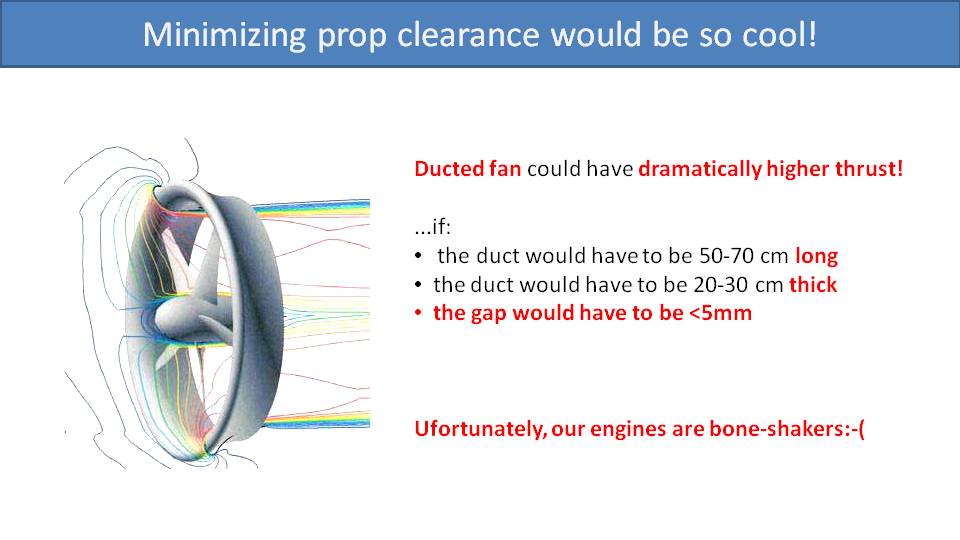
When talking about propeller clearance, we’re referring to the gap between it and the cage. Ideally, it would be like a ducted fan where the clearance is minimal, and the cage is a duct that reduces vortices caused by the propeller tips. This would dramatically increase the thrust and efficiency of the propeller. Unfortunately, according to a NASA study, the duct would have to be more than 50 cm long and 20 cm thick. Then, the gap between the propeller and the duct would need to be less than 5 mm. So, a ducted fan on a paramotor is closer to science fiction than reality. Paramotor engines vibrate a lot. They are true boneshakers, and we need to give the propeller some room to play inside the cage.
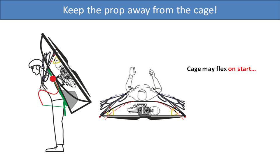
There are a few situations where the propeller could hit the cage. The first of which is right from the start on a forward launch. When you run to lift the glider off the ground, its lines will wrap around the side of the cage. This puts a lot of stress on the cage. If the cage is too flexible, it will be pushed backwards and squeezed in like an oval. In the worst case, the propeller will strike the cage. This could damage the netting, the cage, or the propeller itself and ruin your day.
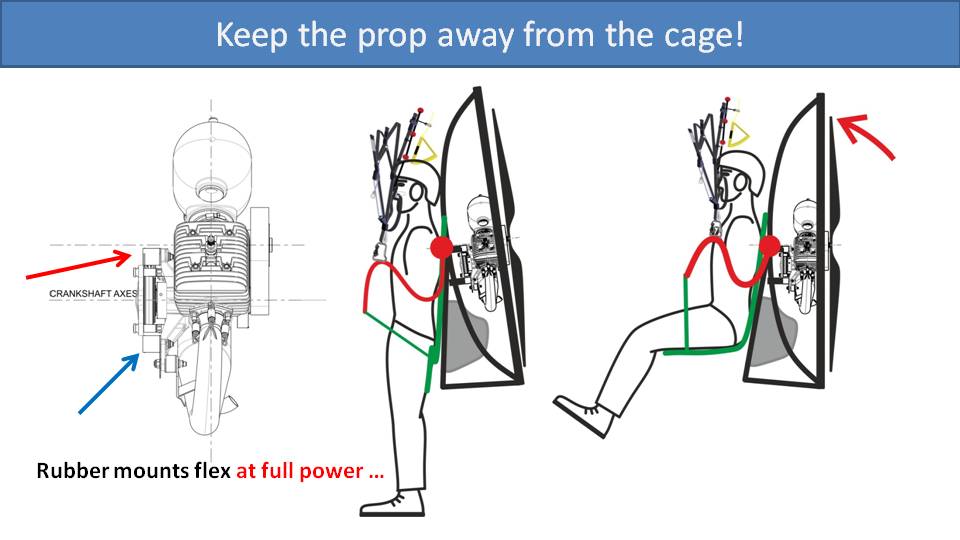
This may surprise you, but the engine flexes within the cage, even under full thrust. Most paramotor engines on the market, including the Vittorazi Moster Plus displayed here, are designed with the thrust axis at the top of or above the rubber engine mounts. Because of this, at full throttle, the top mounts will be compressed, and the bottom mounts will be stretched. This causes the motor and propeller to slightly dive forward into the cage under full power. For this reason, we have mounted the engine into the SCOUT in a strange manner. In the center picture, notice how the gap between the propeller and the cage is larger at the top than at the bottom. In the picture on the right, you can see that when power is applied, the engine tilts forward due to this effect and is now properly aligned with the cage.
Also, some propellers flex under full throttle. In fact, the E-Prop that we sometimes use on our SCOUTs flexes quite a bit because it is so light. So, they design their propellers with a slight curve towards the back to compensate for their flexibility at full load.
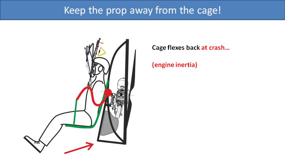
The final situation where a spinning propeller can strike the cage is on a failed launch or landing. If the cage hits the ground hard, it will suddenly stop. However, because the motor is on rubber mounts, its momentum will allow it to continue to move within the cage. In some cases, it can travel far enough such that the propeller will strike the bottom of the cage.
The industry standard is at least 7 cm of gap between the propeller tip and the cage when it’s made of a rigid and strong material. With more flexible cages, this should be increased. The larger this gap is, it will reduce the likelihood that the propeller will hit the cage in any of these situations.
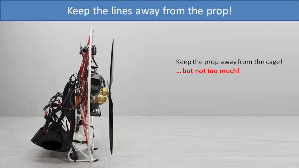
But there can be too much of a gap. Moving the propeller far behind the cage greatly increases the chances of it tangling the glider lines on takeoff or right after landing.
So, if putting the propeller too close to the cage is bad, and moving it too far away is bad, then what is the solution?
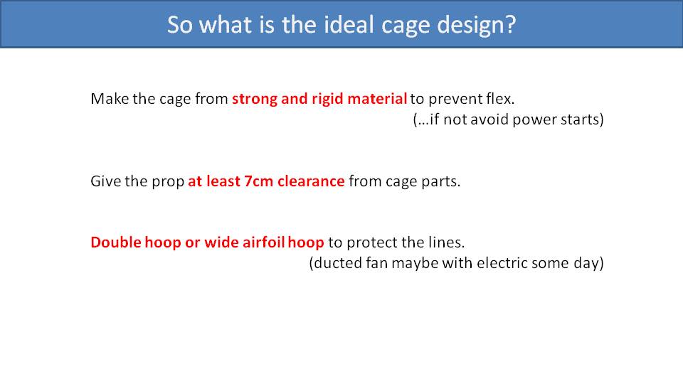
Ideally, the cage is made from a strong material. Otherwise, you should use a clutched motor and avoid power forward launches. Even with these precautions, accidents can still happen. Miro once owned a Miniplane, which he really enjoyed. But he knew it had this issue, so he never applied throttle until the glider was above his head. On one occasion, he ran into deeper snow than he was expecting. As he fell over, his lines pressed up against his cage and the spinning propeller struck it.
Next, even with a strong and rigid cage, there should be at least 7 cm of clearance between the propeller and the cage to allow for flexing of the rubber engine mounts.
Finally, a double hoop design, or a wide airfoil design, like the SCOUT One Carbon, can give the propeller room to play within while providing added protection from the lines.
But we can still dream about that day we all have ducted electric fans on our paramotors.
How much power do you need? That is probably the first question asked when getting into this sport. It took me about 6 years and 8 different engines to finally figure out the power I need for my flying style. I can make it easier for you. –Miro
Part 28: How Much Power Do You Need?
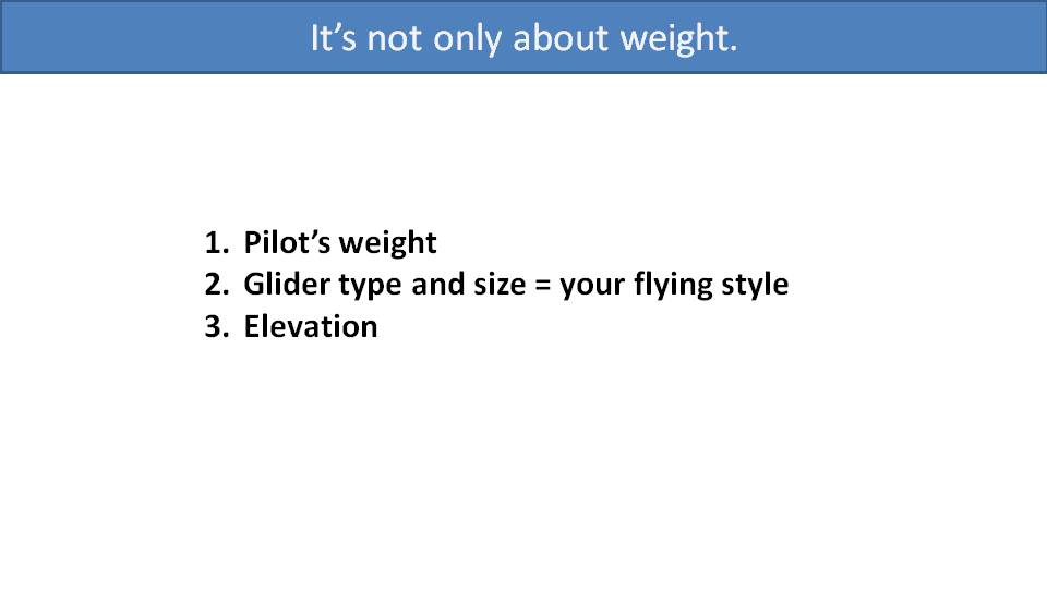
Although your weight is a large consideration when choosing an engine size, there are more factors. For example, Miro’s weight has been about the same over recent years, yet he has gone from 27hp, down to 20hp, all the way up to 36hp and then back down to 27hp because he kept changing flying styles, glider types and glider sizes. Along with weight, glider type, and flying style, you also need to consider your elevation when choosing an engine size.
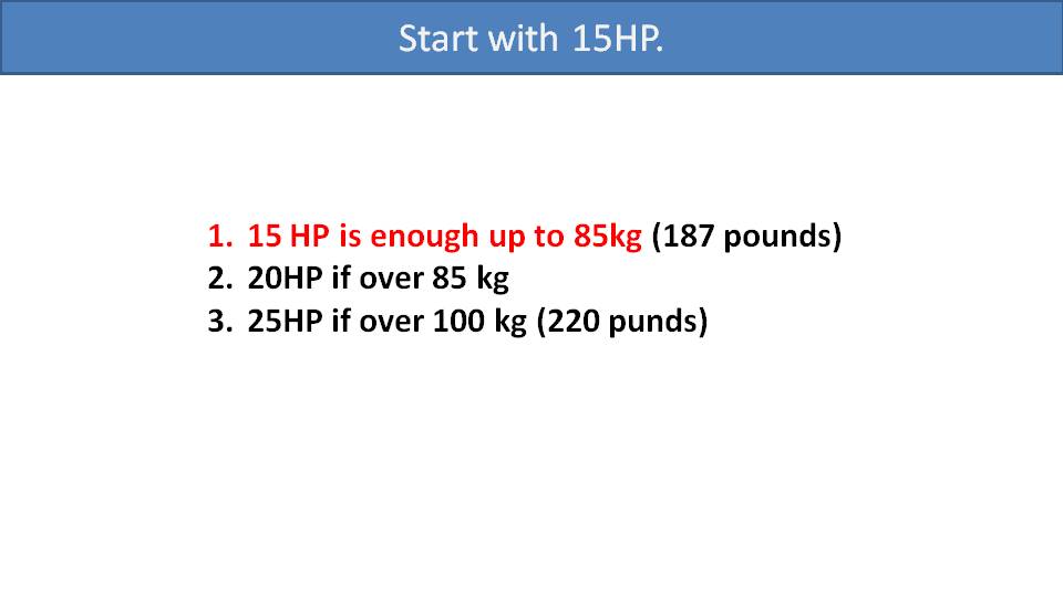
We will use the pilot’s weight to select a baseline amount of power and then make some adjustments for glider type, flying style and elevation. For pilots up to 85kg, 15hp is a good baseline. Heavier pilots up to 100kg should start with 20hp and those over 100kg should start with 25hp.
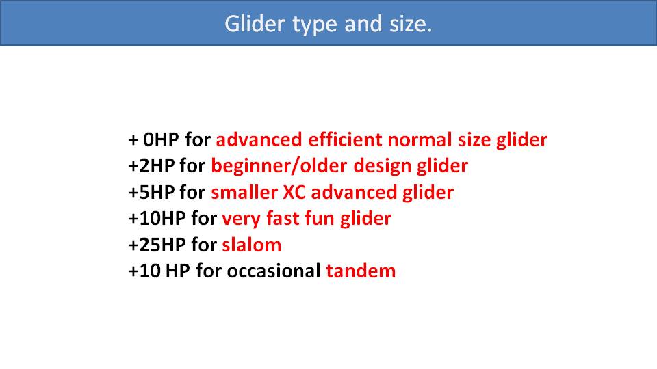
From our baseline, depending on the glider type and flying style, we may need to add some more power. But an 85kg pilot, like Miro, should be fine with that 15hp baseline if he’s flying an efficient advanced glider properly sized for him. Beginner gliders sometimes need a little more power since they don’t glide as well. But in general, the smaller glider you use, the more power you will need. And if you grab a fast-and-fun freestyle glider, you will want to add up to 10hp. Slalom gliders are in a completely different category. There is never enough power for slalom racing, so double the size of the engine if you can. If you take the occasional tandem flight, try to add another 10hp.
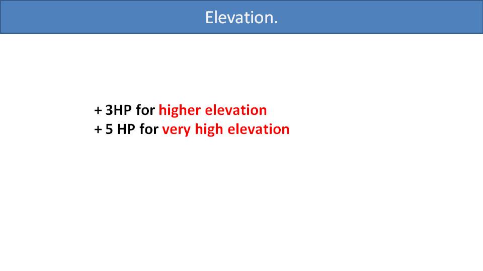
Elevation is the last consideration. If you often take off a high elevation, perhaps well over 1000m, then you should add another 3hp to 5hp to your total.
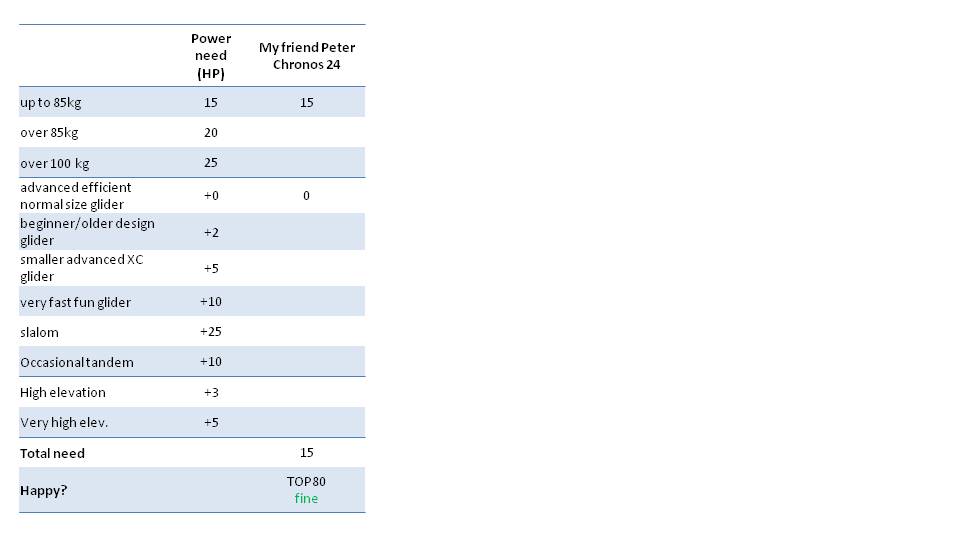
Let’s work through a few examples to show how this would work. We’ll use our friend Peter in the first example. He weighs about 85kg and has been happy flying his 15hp Miniplane Top 80 with his properly sized, advanced cross-country glider. But he’s planning to upgrade to a smaller, faster glider, so he should start thinking about a bigger engine.

For our second example, we’ll look at Miro while flying the Icarus Race. It’s a 1000-mile cross-country unsupported adventure race. So, Miro had to carry all his camping gear and extra fuel with him. Adding the weight of his bivouac gear and extra fuel to his body weight put him just under 100kg, starting him with a baseline of 20hp. Then, he chose a glider that was rather small for that much weight, a 22m Ozone Viper 3. That adds another 5hp to his requirements. On the Icarus Race, his highest elevation takeoff was well over 2000m, adding another 5hp for a total of 30hp. He flew with the 27hp Vittorazi Moster Plus, which was a shade underpowered for this adventure. Imagine him running like a gazelle on the Serengeti to be able to take off at high elevations.

Our next example is Miro flying back at home. Without the weight of the bivouac gear, he’s back at a 15hp baseline. He usually flies an 18m Dudek Snake, which is a small spicy glider for fun and aggressive flying. As this is fun freestyle flying and not slalom racing, add 10hp for a total of 25hp. He used to fly the Polini 250 with 36 horsepower, which was amazing fun, but much more horsepower than he needs. So, downsizing to the 27hp Vittorazi Moster Plus was a good choice for a more comfortable engine to carry.

Now we’ll add our friend Shane. Shane weighs about 100kg, so his baseline is 25hp. He flies a 20m Niviuk Doberman, which is a small spicy glider for him. He also takes off at higher elevations in Utah. So ideally, he would have a 38hp motor. He flies with the Vittorazi Moster Plus, so that’s definitely underpowered for him. He’s a fantastic pilot, so he makes it work and has lots of fun. But he can’t push full speed bar and maintain altitude.

Our friend Steve is 90kg, which gives him a 20hp baseline. He usually likes to fly cross country on his properly sized glider. But he occasionally takes passengers on tandem flights. He also has a Moster Plus. So, he has plenty of power for his solo flights, but is slightly underpowered on tandem flights.

Finally, let’s look at Alex Mateos, world champion slalom racer. With slalom racing, there is never enough power, regardless of your weight. Alex flies the 36hp Polini 250, and I’m sure he’d like more.
What we’re trying to illustrate is how your power needs change with different gliders, flying styles and situations. So, perhaps a lighter pilot getting into the sport might opt for a more powerful engine. This will give them the option to downsize their glider or fly from more demanding locations in the future. On the other hand, larger engines can be more challenging, too. They are heavier and sometimes are difficult to start. This is why we see the Vittorazi Moster Plus as the most popular engine as it is a nice compromise for many pilots.
There are many design parameters with propellers, and each has its tradeoffs. So, it can be tricky to balance them all for the best propeller. –Miro
Part 29: All About Propellers
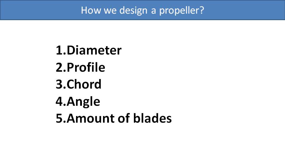
Several parameters must be taken into consideration when designing a propeller. They include its diameter, profile, chord, angle of attack, and number of blades. And each of these needs to be balanced with the others. If you have a propeller that is already working well, you cannot just change one parameter to make it better. For example, if you just increase a propeller’s diameter and keep everything else the same, the propeller will have more drag and the engine will not have enough power to reach its maximum RPM. The same thing will happen if you increase its angle of attack and keep everything else the same.
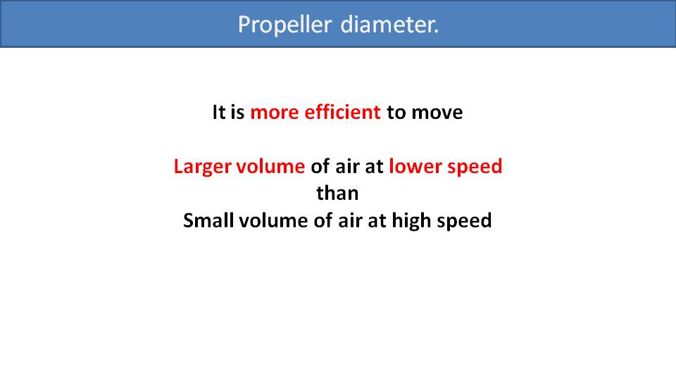
Let’s start with the diameter. To any flying object, speed is enemy number one. This is because drag from wind resistance increases exponentially with speed. The same holds true for a volume of air moving within a larger airspace. If you move a volume of air quickly, the edges of the airflow will create vortices and drag. Thrust is a product of the volume of air and its speed. So, for a given amount of thrust, it’s more efficient to move a large volume of air at a lower speed than a small volume of air at a higher speed. Applying this to propellers, this means a larger propeller will be moving a larger volume of air. So, a smaller propeller will have to move its smaller volume of air much faster to achieve the same thrust. Because of the increased drag of that air volume going faster, it will be less efficient. We can see this in a diagram.
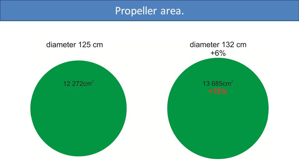
Let’s compare a 125cm propeller, which is common on paramotors, to the 132cm SCOUT propeller. Even though its diameter is 6% larger, its area is 12% bigger because it’s a square function. It gets a little more complicated, however, because not all the propeller’s area is functional.
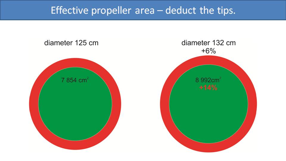
Due to the vortices they create, a propeller’s tips are ineffective. This is like how the tips of airplane wings don’t provide any lift. So, let’s deduct the last 12.5cm on each side of the propeller from its effective area calculation. Now, the difference in effective area between the larger propeller and smaller propeller goes up to 14%. We can all hear you screaming at us that the center of the propeller is also useless and not generating any thrust.
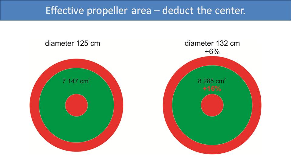
Yes, the center of the propeller doesn’t provide much thrust due to its slow linear speed. It’s also behind the engine and in the wind shadow of the pilot, so it doesn’t get much airflow either. Let’s assume an inside diameter of 30cm where the propeller is ineffective, even though it is probably bigger. Now, the effective area of the larger propeller is 16% bigger than the smaller propeller even though it’s only 6% longer.
This doesn’t technically mean that this larger propeller is 16% more efficient than the smaller propeller, though. It just means that the larger propeller moves 16% more air with every rotation. So, for the same amount of thrust, the engine can spin much slower. Remember that the slower the air mass moves, the less of its thrust is wasted on drag. So, the engine spins slower, is less wasteful, and therefore much more efficient.
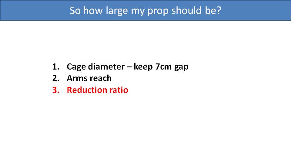
How large of a propeller should you get then? The larger, the better! Of course, there are some practical and safety limitations. We recommend at least a 7cm gap between the propeller tip and the cage as a safety margin. If you choose a larger cage to get a larger propeller, make sure it’s not much larger than your arm span and doesn’t impede your lines on takeoff. Also, be aware of your leg and ground clearance while running. Otherwise, go as big as you can. You will need to pay attention to the reduction ratio between your motor and propeller because it determines how fast your propeller will spin.
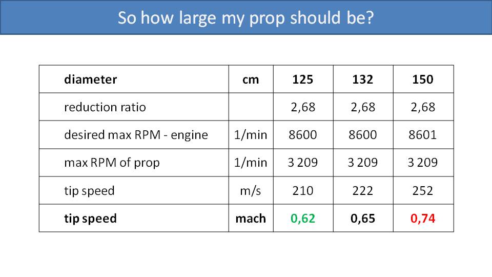
Let’s look at these three examples to help understand how the reduction ratio works with propeller length. We’ll compare a 125cm propeller, which is a common size in paramotors, a 132cm propeller like the SCOUT, and a 150cm as an extreme example. This chart is using the 2.68 reduction ratio and 8600 maximum RPM of a Vittorazi Moster Plus engine. With that ratio and engine speed, it translates to a maximum propeller speed of 3209 RPM. Doing a bit of math, the tip speed of the 135cm propeller will be Mach 0.62. The 132cm propeller tip speed will be Mach 0.65, and the 150cm propeller tip speed will be Mach 0.74. The sweet spot for propeller tip speed is Mach 0.62. As the tip speed increases, its noise increases. This is probably why our 132cm propeller barely didn’t pass Germany’s sound requirements during testing, but the 130cm E-Prop did. You can see here that you would want to reduce the reduction ratio to get the 150cm propeller’s tip speed down to an acceptable level.
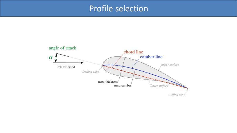
The next consideration is the profile of the propeller. Different manufacturers choose different profiles based on the propeller material and other tradeoffs they want to make. Here are three propellers that we often use with Vittorazi engines.
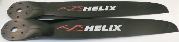
This is a Helix propeller, which has a beefy profile.
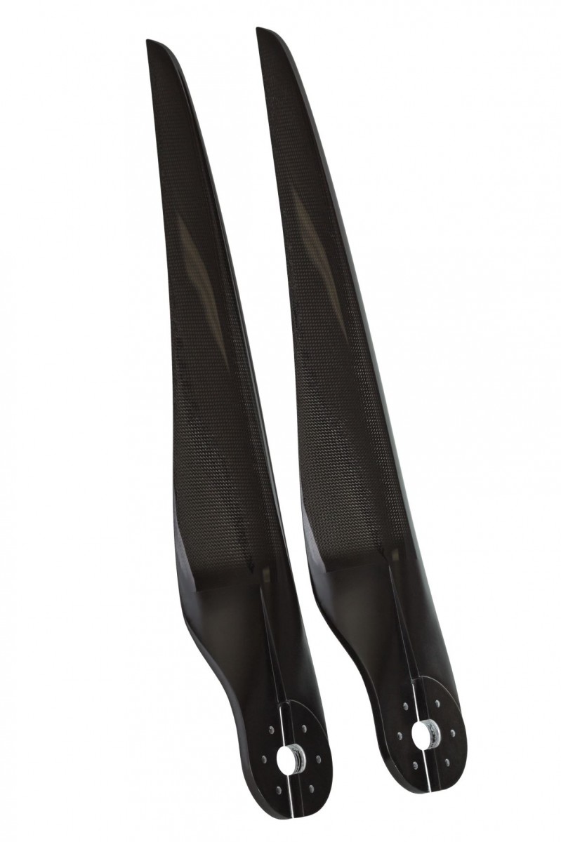
Next is our SCOUT 132cm propeller. Its profile is similar to the Helix, but thinner.

Finally, this is the E-Prop, which has a completely different and very thin profile.
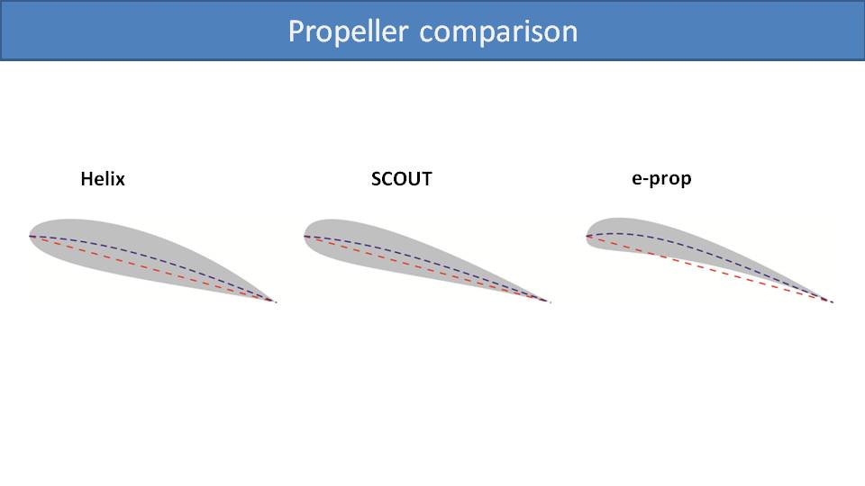
Not only does the thickness of the profile matter, but its overall shape does, too. We have some generalized diagrams of the profiles of these three propellers to compare. We can see the beefiness of the Helix propeller and how the SCOUT propeller is thinner, but similar. Then, the E-Prop is quite a bit different. They have an interesting production technology they use to manufacture propellers with a very thin profile. Their other difference is in the shape of the bottom surface of the propeller. The exaggerated curve of the blue camber line allows the bottom surface to be curved inward in a concave manner. In the end, these are three different profiles that serve the same purpose.
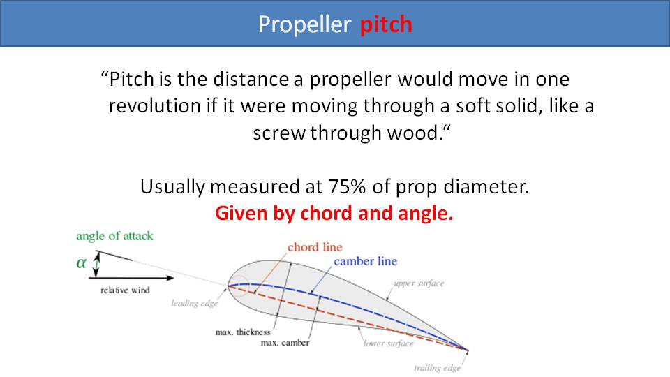
The last consideration is the angle of attack and pitch of the propeller. Its pitch is the distance the propeller would travel forward in one revolution if it cut the air perfectly. To determine this, we look at the angle of attack and length of its chord line. The chord line is the straight line from the propeller’s leading edge to its trailing edge as measured at 75% of the propeller’s radius.
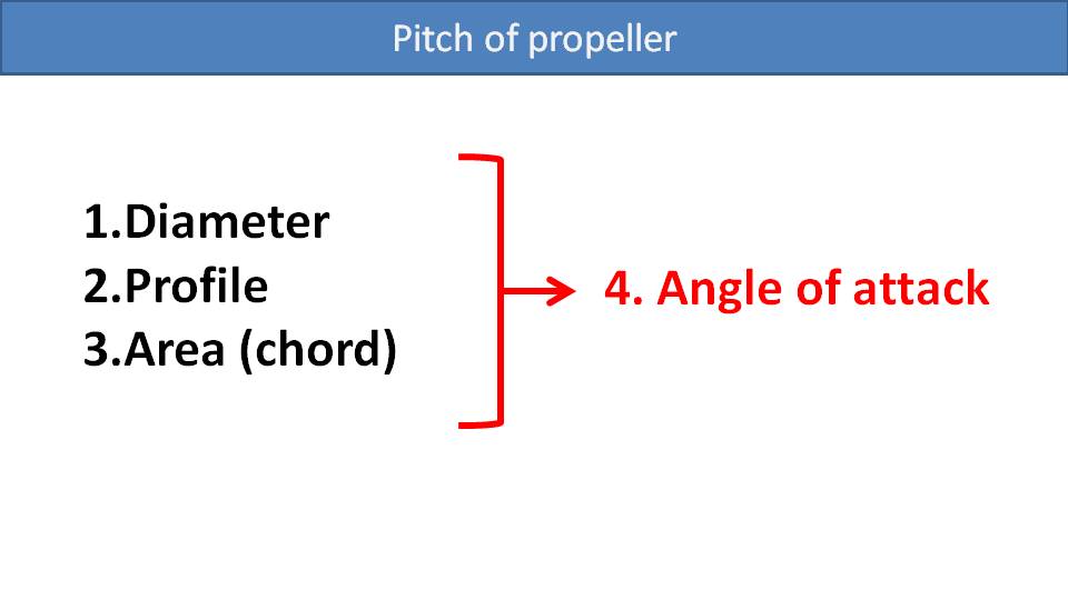
When designing our SCOUT propeller for the Vittorazi Moster Plus, we started with a few key design decisions that we knew we wanted. We opted for a 132cm propeller, which is the largest that could safely fit into the SCOUT frame. We chose a profile that was somewhat inspired by the E-Prop and then designed a beautiful blade area. Then, the last thing we needed to determine was its angle of attack. We can do the modeling and calculations we want for this, but you never truly know how it will behave until you test it.

Therefore, it really helps to make the final adjustments using a propeller with an adjustable angle of attack. If we adjusted the angle too high, then it increased the load on the engine and it couldn’t reach its maximum RPM. If we adjusted the angle too low, then the engine would rev far beyond its maximum rated speed of 8600 RPM and damage it. So, we made a series of adjustments until we found the sweet spot that put the right amount of load on the engine. Once we figured out the angle of attack we wanted, we designed it into our fixed-pitch propeller that’s easy for everyone to use.
How are you supposed to know which propeller is better for you? As a rule, larger propellers are better than smaller propellers. They deliver more thrust with higher efficiency. After that, the most common way to compare propellers is using a static thrust test. You mount a paramotor with the propeller onto a test bench that can measure the force it produces and rev it up. But this test has limitations. Environmental factors like temperature, humidity, and air pressure influence the measurements. Also, the performance of the engine can alter the results. So, if you measure two different propellers with the same engine on the same day, you can draw some conclusions regarding which propeller is more efficient than the other. But even then, this test is not always accurate because a propeller’s performance while it’s stationary on the ground will be different than when it’s cutting forward through the air.
We don’t believe these static thrust tests are useful, so we don’t do them. There are better ways to compare propellers.
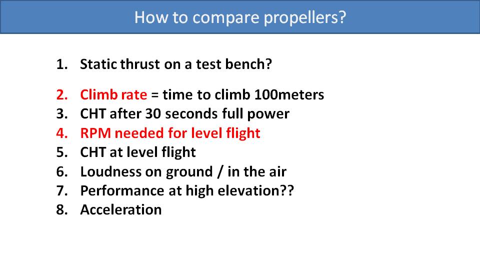
The first valuable measurement we like to do with propellers is measure their climb rate. We do measurements on the same day, with the same glider, the same pilot, and the same weight. We let go of the brake toggles to make sure they don’t interfere and then time how long it takes to climb 100 meters. This is a true and accurate measurement of dynamic thrust. You won’t be able to use this to calculate how many kilograms of thrust it produces, but you can accurately compare the dynamic thrust between propellers.
Next is to measure the cylinder head temperature (CHT) after a 30 second climb. These air-cooled 2-stroke paramotor engines are sensitive to high temperatures, which is why most paramotor propellers have extra cooling flanges to pull air across the engine head.
Then, we look at the engine speed, in RPM, needed for level flight on a given day. This is a good indication of the propeller’s fuel efficiency. Obviously, the lower, the better.
We also check the cylinder head temperature at level flight, but that usually isn’t an issue.
When looking at the climb rate, cooling ability, and cruise RPM across the Helix, the SCOUT and E-Prop propellers, we did not notice any major differences. But there are some differences, like loudness.
The loudness of a paramotor, in decibels of sound pressure level (dB SPL), plays an important role in Germany and Austria where it is a part of the certification. The SCOUT propeller didn’t pass this certification. It was slightly above the limit, probably due to the two centimeters of extra length versus the others. So, its tip speed is a little higher, making a little louder.
Miro has also noticed some performance difference at high elevation. When he was flying the Icarus Race, there were some high altitude passes over mountain ranges. He got the sense that the E-Prop had slightly better performance at those high elevations with low air density. But this was a subjective assertion since he wasn’t able to do an official comparison under identical conditions. It just seemed that the SCOUT propeller wasn’t quite as efficient as the E-Prop in these conditions.
Finally, we look at the acceleration of a propeller from idle to maximum RPM. This is a function of the weight of the propeller and how it’s distributed. The more mass you need to accelerate, the more energy you need to apply, and the longer it takes to spin up. The E-Prop is the lightest and accelerates the quickest. The SCOUT propeller is next, and the Helix is the heaviest of these three. For cross-country pilots who like to cruise, this is not an issue. If you like to go on and off the throttle for powered wingovers, freestyle, or slalom flying, then you might prefer a lighter propeller.
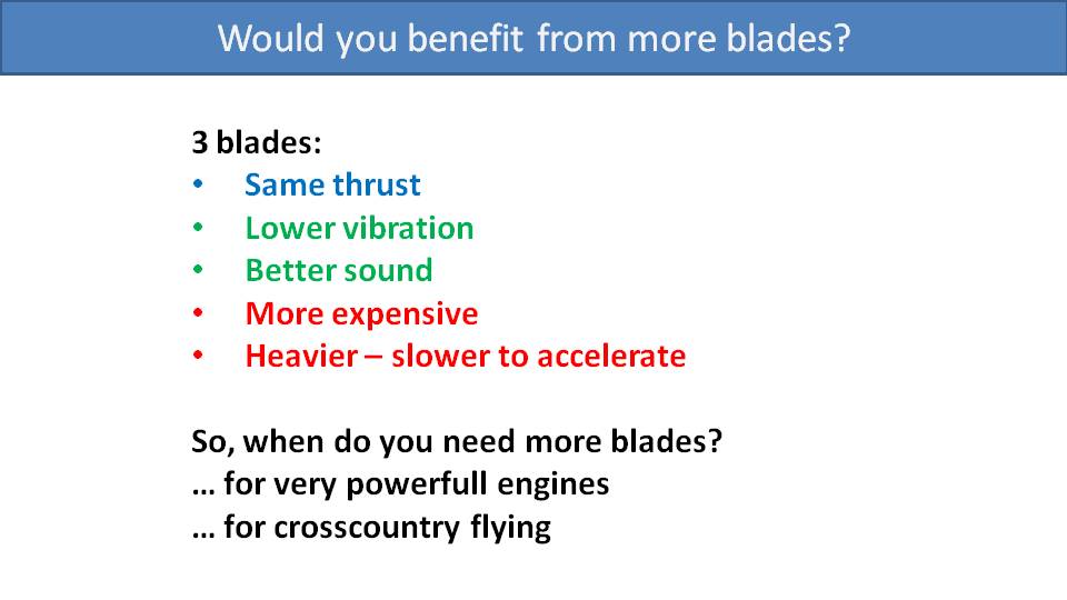
The last consideration is the number of blades. Are three-blade or four-blade propellers any better than two-blade propellers? We studied a few three-blade propellers and concluded that they didn’t add any thrust. The extra blade adds drag and the motor can’t spin as fast, which resulted in about the same thrust. They vibrated much less, lending to a silky-smooth flight, which was nice. We measured the loudness of a prototype three-blade SCOUT propeller with a sound level meter, and it was the same as our two-blade propeller. It sounded different, though. Its tone was higher and sounded like it belonged in a MotoGP race, which we thought was cool.
There are some drawbacks with three-blade propellers. First, they are more expensive as three blades obviously cost more than two. They are also heavier. So, if you like going on and off throttle frequently, two blades are a better option. However, there are some situations where you must go to three or four blades. If you fly a powerful engine, like a Polini 250, you will need to add another blade or two to make use of the extra power. You also have the option of using wider blades with a longer chord, or a higher angle of attack, but usually going to a three-blade or four-blade propeller is the best option.
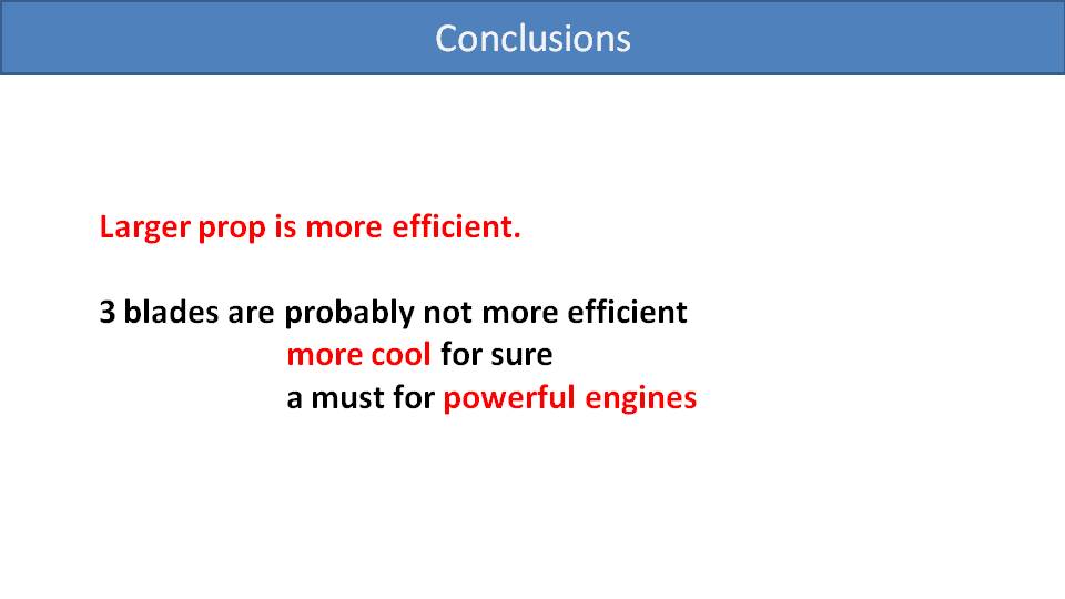
In conclusion, larger propellers are more efficient. We have proven this by theory and with real life experience. Three-blade propellers are not more efficient, but they sound great and are smoother. However, three-blade and four-blade propellers are often necessary with more powerful engines.
It seems obvious that a lighter propeller will be better in the air. But there are other aspects to look at, as well. –Miro
Part 29.2: Propeller Weight
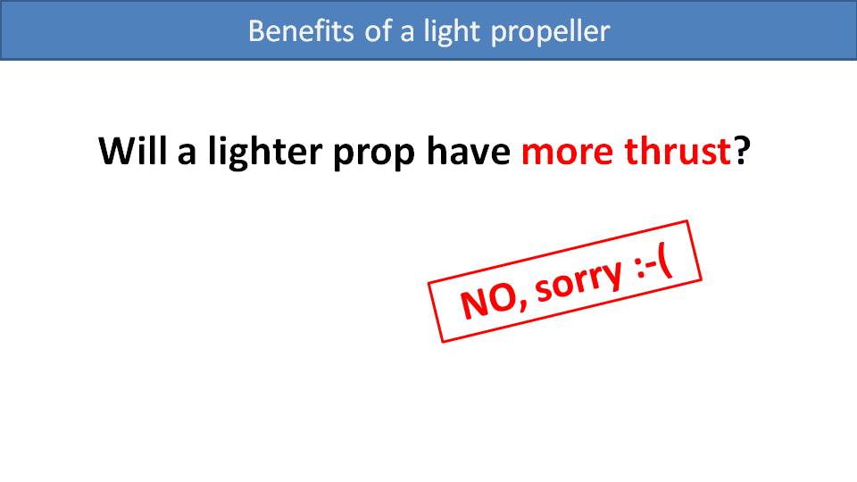
Some pilots believe that a lighter propeller will give them more thrust, but this is not the case. With all else being equal, one propeller can deliver more thrust than another only due to its length and profile. Any weight difference will have no effect on thrust.
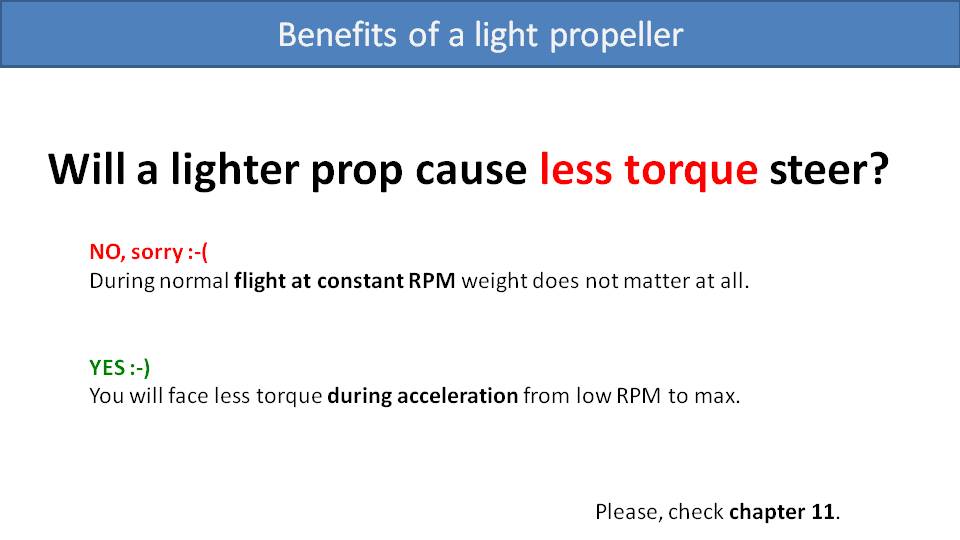
Will a lighter propeller have less of a torque effect? The answer is more complicated and is a “no and yes”. At constant RPM, like at level flight or a full-throttle climb, a lighter propeller will not have any less torque effect than a heavier propeller. This torque effect depends only on the drag of the propeller, which is based on the propeller’s length and profile regardless of its rotating mass. But its weight will influence the torque effect while accelerating the propeller. To accelerate a heavier propeller from idle to full speed, it will take more power for a longer period of time. So, you will be exposed to this acceleration torque effect for longer and it will be stronger. For the fraction of a second it takes to accelerate a propeller, a lighter propeller will spin up faster with less torque effect.
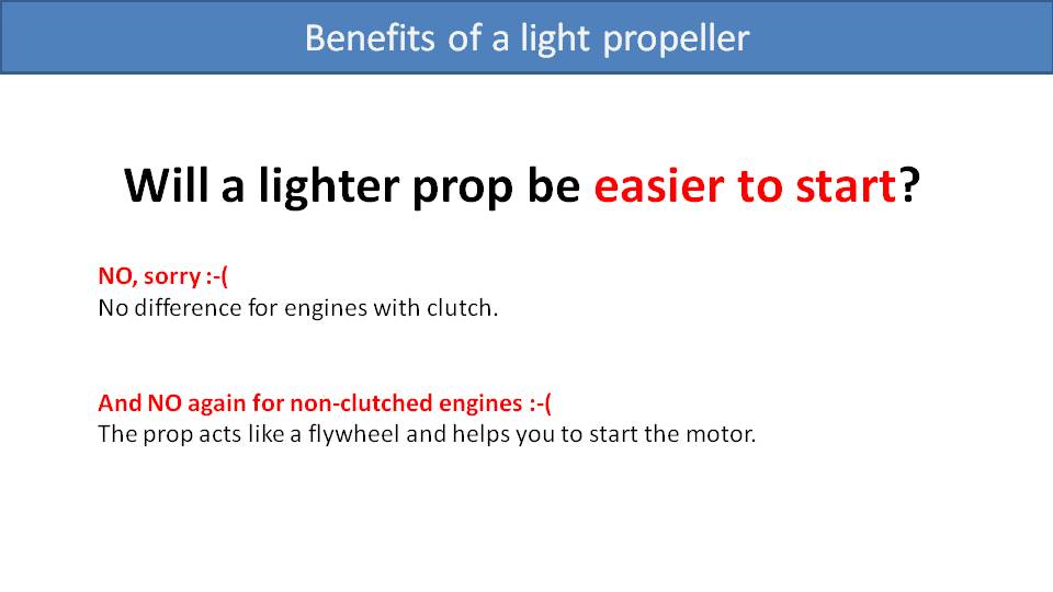
Will an engine be easier to start with a lighter propeller? If the engine has a clutch, then the weight of a propeller has no effect since it won’t be spinning. For engines without a clutch, the weight of the propeller is important. In this case, if the propeller were not attached, it would be virtually impossible to start the engine. On these engines, the propeller acts as the flywheel. When you pull the starter cord, the crankshaft also spins the propeller. The inertia of the propeller’s rotating mass is what pushes the piston through a stroke so that it can start and continue. In this case, a super light propeller would not be beneficial and would only make the engine more difficult to start.
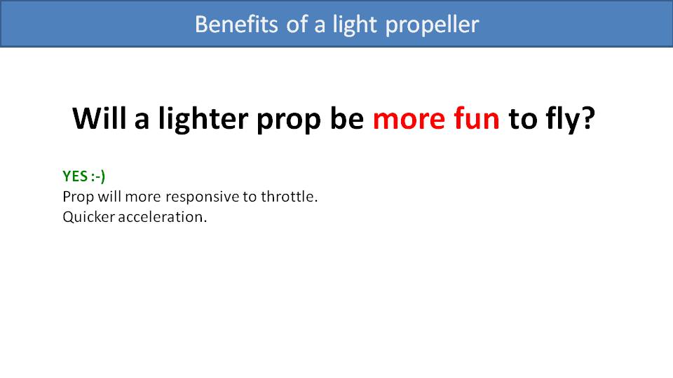
Will a lighter propeller be more fun to fly? The answer in this case is “yes”. A lighter propeller spins up to full thrust faster. So, during aggressive maneuvers when you’re going from idle to full-power, or cruise speed to full-power, you will get there much faster. If you compare a wooden propeller to a lightweight carbon fiber propeller like an E-Prop, the difference is huge, and you will notice it right away. The wooden propeller will have a delayed response when you mash the throttle, and the E-Prop will feel like it jumps straight to full thrust.
So, the main advantage of a lighter propeller is its spin up time, but there is also less acceleration torque. Let’s look at some of the specific disadvantages with lighter propellers, the first of which is durability.
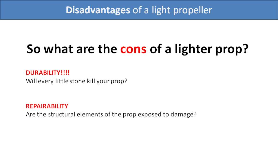
Reducing its weight comes at the cost of having less carbon fiber, less epoxy, and less reinforcement inside. As a result, the propeller will be less durable. When running on takeoff, or when doing a foot drag, little stones can be kicked up and thrown into the propeller. The lighter the propeller, the more likely that an impact with a small stone will cause significant damage. Of course, if you hit a big rock or a bolt falling off your engine, that will rip apart any propeller.
The other issue is repairability. When taking damage to a propeller, you need to pay attention to its structural elements and how well they are protected. As stones hit the leading edge, they can nick it or even chip little bits off. If they damage the structural elements of the propeller, it likely will not be repairable.
[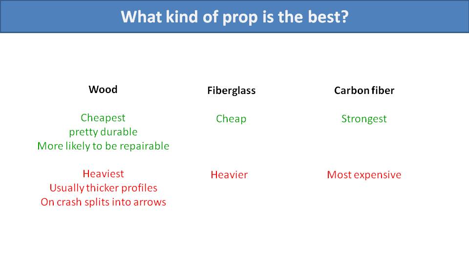
Let’s compare the three basic construction types of propellers for their durability and repairability.
Wooden propellers are the cheapest. They can take quite a bit of damage from stones and are easily repairable. If a stone strikes the leading edge, it will likely only take a little bite out of it. You can fill the gap, balance the propeller and it’s ready to fly again. Because there isn’t an inner structure to damage, leading edge impacts like this are usually repairable. However, they have some disadvantages. Because wood is not as strong as fiberglass or carbon fiber, there needs to be much more material to keep it rigid and strong. So, they will be heavier and will have a thicker profile. And our research showed that propellers with thinner profiles had better performance.
The other major disadvantage of wooden propellers is their behavior in a crash. When they strike something and fall apart, there is a chance they will split into arrows and the centrifugal force will spray them in all directions. This is usually not dangerous to the pilot, but innocent bystanders nearby may be injured.
Fiberglass propellers are often a better option than wooden propellers. They’re relatively cheap and easy to work with. But they too are heavier than carbon fiber propellers.
Our preference is carbon fiber propellers. They are the strongest and lightest, but also the most expensive. However, you can save money on propeller replacement with good training, which is always the best option.
Let’s examine the construction of three composite propellers by looking at some broken ones. We have a fiberglass Helix propeller, and then two carbon fiber propellers: a SCOUT, and an E-Prop. The internal structure of each is quite different.
Let’s start with the Helix. This one is made from fiberglass that is tinted black. They use a product from ParaBeam as their structural core. It is a 3D woven fiberglass fabric soaked in epoxy and cured. It has thick walls that sandwich the 3D mesh in the middle. This keeps it strong and solid while keeping it reasonably light. However, at over 1kg, it is the heaviest of these three composite propellers.
The E-Prop is a very lightweight propeller. Its core is filled with foam and there are two thin layers of carbon fiber on the outside. There is also a carbon fiber reinforcement rib running through the middle. It is very lightweight, accelerates quickly, and is fun to fly. Its profile performs well, especially at high altitudes. The only problem that we have with E-Props is that they are fragile. If you kick up a small stone while running or foot dragging, it might break through the leading edge of the propeller and into the core. At that point, repairing it is unadvised.
Finally, let’s look at the SCOUT propeller. It also has two thin layers of carbon fiber, like the E-Prop, but its reinforcement rib is different. It’s a thicker foam insert soaked with epoxy. The rest of the inside is hollow to save weight. Then, the leading edge is a thick layer of carbon fiber. So, it is more resilient to impacts with small stones and much more repairable. Obviously, this comes at the cost of weight, which is why the SCOUT propeller is a little heavier than the E-Prop.
An important thing to keep in mind is if you ever repair a propeller, you need to rebalance it. One of the easiest ways to do this is to drill a small hole, squeeze in some epoxy and then let it cure. This is only possible with the SCOUT propeller as it is hollow inside. Because of the E-Prop’s foam core, you would need to push a nail or some wire into the hole instead. Please review our YouTube video on propeller repairs for more detail.
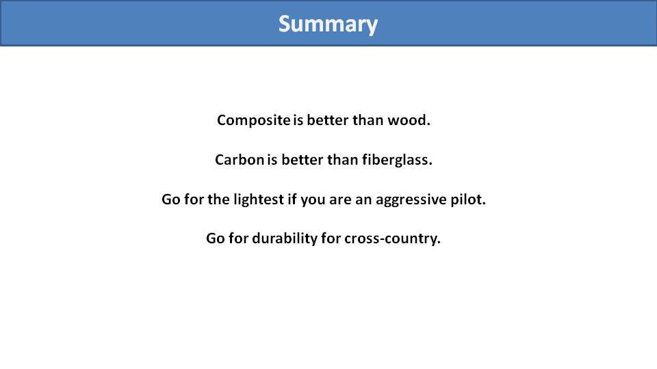
In summary, composite propellers are better than wood in our opinion, and carbon fiber is better than fiberglass. If you are an aggressive pilot and fly from nice grassy LZs free from stones, opt for a lightweight propeller like an E-Prop. It will do great for you and last a long time. Finally, choose a more durable propeller if you are more into cross country flying, travelling, or if you take off from gravel or sand more often. It will be a little heavier, but the SCOUT propeller would be great for you.
Should you prefer a paramotor with a clutch? The answer is yes. It’s a simple and straightforward answer, but the reasoning is a bit tricky. –Miro
Part 30: With or Without a Clutch
We have flown paramotors with and without clutches over the years. Our conclusion is that it’s better to have a clutch, but our reasoning is not obvious. Let’s start by analyzing the pros and cons one by one.
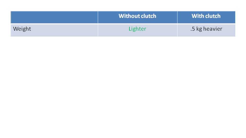
Obviously, adding a clutch will add weight to a paramotor and engines with clutches are usually about a half kilogram heavier. So, we need to determine if their value is worth their weight.
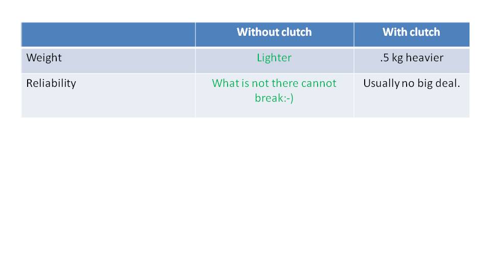
As the adage goes, whatever is not there cannot break. In this respect engines without clutches are more reliable. However, issues with clutches are not common.
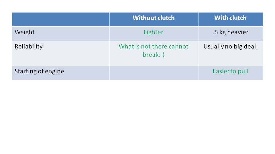
Certainly, engines with clutches are easier to start, and the reason is simple. You don’t waste your energy accelerating the propeller. When you pull the starter cord, all your effort is applied to the engine itself. In fact, we were able to measure this when designing our SafeStart computer. We noticed that when pulling the starter cord on clutched engines, they usually reached about 1000 to 1200 RPM before starting. However, on engines without clutches, they often reached up to 2500 RPM when pulling the starter cord. So, you’re much more likely to start a clutched engine on the first or second pull.
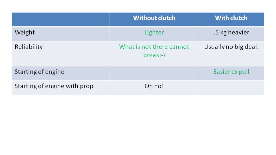
Some may say that an advantage of engines without clutches is that you can hand-start them if the starter breaks. We believe that manually spinning the propeller to start a paramotor is extremely dangerous and not an advantage at all. If your starter is broken, please stay on the ground and fix it. Don’t start it by hand.
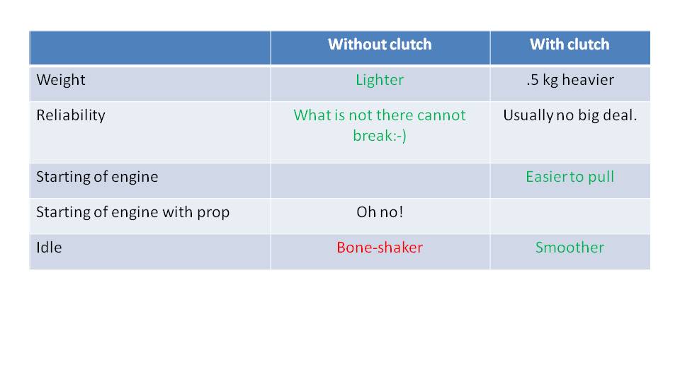
We have noticed that engines with clutches run more smoothly while idling because of the idle speed. Even though Vittorazi recommends an idle speed of 2000 to 2200 RPM on the Moster Plus, we prefer to set it a little higher. When idle is set to 2300 or 2400 RPM, it runs much more smoothly and has less vibration. This also puts less stress on the rubber mounts and the exhaust. On engines without clutches, you can’t run the idle this high because the propeller would always be pushing you.
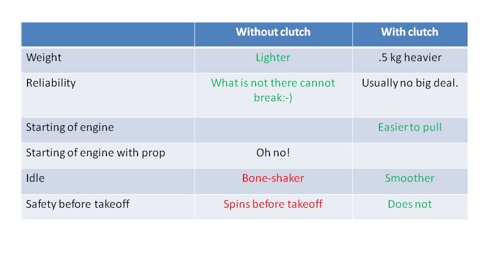
The primary reason that someone chooses an engine with or without a clutch is safety. There is certainly a safety benefit if the propeller is not spinning on your back while preparing for takeoff. So, while you are hooking into your glider, checking your lines, looking around to ensure your airspace is clear, and then starting your launch, the propeller is not spinning and potentially hitting something.
Ground starting your paramotor is starting it while it’s just sitting by itself on the ground, and not on your back or in a rack. This is potentially dangerous, and many pilots have been maimed by doing this. The SCOUT has the SafeStart computer to help protect you. But, if the engine has a clutch, you can also strap the propeller to the frame to protect yourself from a runaway motor. This is not possible on paramotors without clutches.
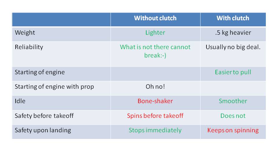
Clutched engines have a slight safety disadvantage while landing. When you kill your engine, the propeller will continue to spin for a while which increases the risk of them tangling your lines.
So, it’s not a straightforward answer to choose to have a clutch or not. We have tried both over the years and had a hard time making a definitive rational conclusion. In the end we believe that the biggest benefit of a clutch is psychological. It makes us feel more at ease on the ground before takeoff. So, if you feel less stress on the ground and less urgency to take off, you are more likely to have a smooth clean takeoff. We have also noticed that students perform much better on engines with clutches. They just keep calm and carry on.
Most paramotors out there are equipped with a manual starter. Yet, there are more and more paramotor and engine manufacturers that include electric starters. Let’s investigate the details to figure out your best option. –Miro
Part 31: Manual or Electric Starter
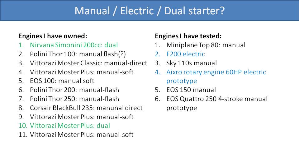
This is a list of all the engines that Miro has owned or tested. He started with the dual start Simonini Nirvana 200cc. Then, he progressed through a series of manual start engines, some small and some up to 250cc. He flew the Moster Plus with a dual start for a while, but finally settled on one with a manual start. He has also test-flown several more engines. Most of them were manual start, but two had electric starters. So, he has a lot of insight that he can share with us.
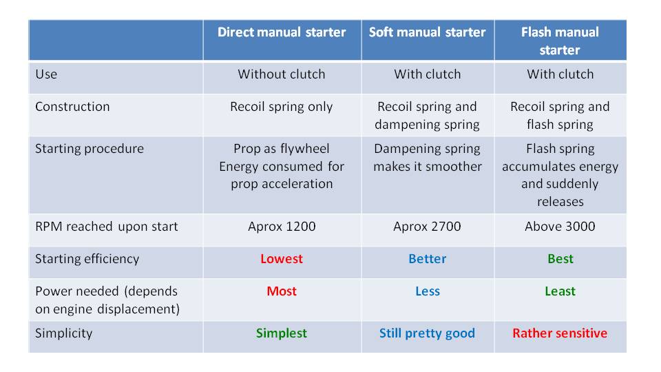
First, we need to understand that there are three types of manual starters:
· Direct starter
· Soft starter
· Flash starter
There are differences in their construction and in their use cases. Direct manual starters are used for engines without clutches, and soft and flash starters are used with engines with clutches. The direct manual starter is the simplest design. The starter pulley is connected directly with the flywheel and the propeller. So, as you start pulling the starter cord, you immediately and directly feel the resistance of the engine and propeller as you spin them.
With the soft manual starter, there is an additional spring between the starter pulley and the flywheel. When you start pulling the cord, this spring absorbs some of the initial tension and lets you build your pulling force gradually. As you are completing the pull, the spring is then releasing its tension for a little boost.
The flash starter is a little different. During most of the pulling motion, you are not engaging the flywheel at all. Instead, the high-tension flash spring is absorbing all the energy. Once the flash spring is fully tensioned, it quickly releases its energy into the flywheel. So, all the energy you put into the spring is released at once while you complete your pull. This gives a sudden kick to the flywheel to maximize its speed and help the engine start.
For these three manual starter types, you’re always just pulling the starter cord, but the output is different. With the direct manual starter, your effort is transferred linearly and directly into spinning the engine and propeller. By our measurements, you typically can spin the engine to about 1200 RPM when starting with a direct manual starter.
Using soft manual starters with clutched engines, you’re not spinning the propeller at all. Your energy is applied only to the flywheel and engine. We have measured that you can spin them up to 2700 RPM for a short moment with soft starters.
The flash starter is even better because it releases all the energy stored in the spring at once. We have seen that when you pull the starter cord on a flash starter, that the engine can spin greater than 3000 RPM for an instant.
Clearly the starting efficiency is best with the flash starter, followed closely by the soft manual starter. With these two types of manual starters, you have a high probability of starting the engine on the first or second pull. You need the most strength to pull a direct manual starter without a clutch. You don’t get any help from starter springs and you need to accelerate the propeller as well. Clutched engines require less strength to start and are easier.
Regarding simplicity, direct manual starters are quite simple and require little maintenance. Soft starters are also simple. Flash starters are more complicated and are known to require more maintenance.
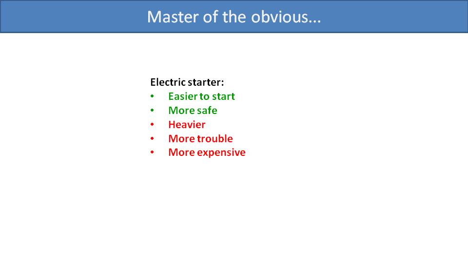
Coming back to the electric starter, its advantages are obvious. It is effortless to just push a button and your engine starts. Some believe it’s safer because you can wait until after you’ve finished your preparations and hooked into your glider before starting it. But it’s similar for clutched engines since their propellers don’t spin while idling. Regarding their disadvantages, electric starters are heavier since they add the electric starter motor, its battery, and their electronics. Also, if the electric starter system is equipped with in-flight battery charging, there is an additional generator coil. These are all very technical parts that can wear down, break, and cause you trouble. Finally, electric starters are more expensive.
When listing all the motors that Miro owned, most of them were manual start. If you asked him if he wished they had electric starters, he mostly would say, “no”. His first motor, the Simonini 200cc was a dual start and he used the electric starter all the time. It was a nice convenience, but he switched to manual starters to save the weight on his back. The only motors he had issues starting manually were the Polini 250 and the Corsair BlackBull 235. He agrees that it would be nice to have electric starters for those motors, but they’re already so heavy, that it’s not worth the weight. The BlackBull 235 he had was exceptionally difficult because it was also a direct manual starter and required an extra-long pull. He even had to reposition the pulley on the starter cord higher to extend his pull.
He flew the Vittorazi Moster Plus with dual start for a while, and he thought it was a nice setup. The added weight was acceptable. But he feels that pull starting the Moster Plus is so easy that he switched back to a manual start to save the weight and complexity. So, for him, the electric starter was just unnecessary.
With regard to the other engines he tested with electric starters, one was the F200. It worked well when he flew it, but there were a few occasions when his friend was grounded because his starter battery was dead. The other was a very special engine, the Aixro rotary engine with 60hp. It was a racing prototype adapted for paramotor use, and probably would have been impossible to start with a manual starter. That was one crazy unit for one crazy pilot, our friend Javi Malaguita.
Another interesting engine he recently tested was the EOS Quattro 250. It’s a four-stroke engine with a manual starter. Despite being 4-strong with a higher displacement, it was surprisingly easy to start with a manual starter.
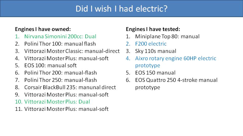
For engines with a direct manual starter and no clutch, you will probably wish for an electric starter. If you have only an electric starter, you will probably wish for a dual start for those days that the battery is dead. For engines up to 150cc, an electric starter is unnecessary for nearly everyone. For engines up to 200cc, an electric starter is a nice convenience and might be necessary depending on your physical condition. However, the added weight might be a burden. For engines over 200cc, you will likely wish you had an electric starter, but it will be a difficult tradeoff on a setup that is already very heavy.
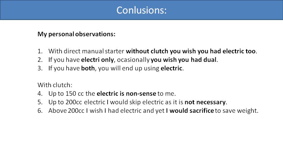
At first glance, the extra kilogram of weight for an electric starter might not seem that much. And on a normal day with a local flight, it won’t be a big deal. But we’ve noticed that when you’re fully loaded with a big engine, or a full tank of gas, or bivouac gear, you really start to notice every kilogram. It seems that above a certain threshold, each kilogram counts for two or three. So, take that into consideration with your flying style and adventures you’d like to go on before deciding on an electric start.
When choosing a paramotor, the engine choice makes a huge difference. But it’s not just about power, weight, clutch, and manual vs. electric start. There are other aspects to consider. –Miro
Part 31.2: Engine Cylinder Position
Usually when choosing an engine, you worry about things like its thrust, weight, vibration level, whether it has a clutch, how smooth its power band is, and so on. None of these are affected by the position of the cylinder. Yet, different cylinder positions do have benefits and disadvantages.
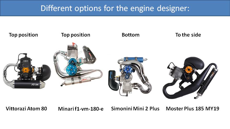
There are three primary options that engine designers use. The first two engines here have the cylinder on the top. Or the cylinder can be at the bottom or to the side.
Let’s start with the cylinder at the top. This design is usually used for small engines like the Vittorazi Atom 80 pictured here, or the Top 80 used on the Miniplane. The benefit of this design is that it’s compact, which also makes it good looking. Its major disadvantage is that it needs to have forced air cooling. The reason is that the cylinder head is too close to the center of the propeller. The center of the propeller does not generate any airflow that can be pulled across the cylinder to cool it, so these engines need forced air cooling. For this, the cylinder head is covered with a carbon fiber shroud. Then on the other side there is a fan driven by the crankshaft which pulls air through the shroud and across the cooling fins of the cylinder head.
Another option to improve cooling for an engine with the cylinder at the top is to mount the reduction pulley at the bottom, like the Minari F1-VM motor in the second picture. In this design, the center of the propeller is moved further away from the cylinder head increasing the airflow and cooling for the engine. The disadvantage of this design is that the reduction pulley, where the propeller mounts, must stay in the center of the paramotor. So, the cylinder head will stick up rather high above the frame of the paramotor. This makes it bulkier, especially when breaking it down for transport.
Another option is to simply turn this design upside down, like the Simonini Mini 2 Plus. This is like the Minari, but just flipped 180 degrees. So now, the cylinder is at the bottom and the reduction pulley is at the top. Again, this has excellent airflow and cooling across the cylinder head because it’s further away from the center of the propeller. But the cylinder head extends quite low and takes away from the space for the fuel tank. Special care must also be taken to ensure there is a sufficient gap between the engine and the fuel tank. The biggest issue with this design, however, is that if you over-prime the engine, fuel will pool onto the spark plug and quickly flood the engine. At that point, you must remove the spark plug, clean it, dry it, and reinstall it before the engine will start.
Our favorite engine is the Vittorazi Moster Plus, in the fourth picture, which is a compromise between these two solutions. Its cylinder is to the side, but slightly upward. That way, the spark plug won’t easily flood if you over prime it. Notice that the distance between the cylinder head and the reduction pulley isn’t as far as in the Minari or Simonini motors, and it won’t get as much airflow. So, we recommend adding a cooling shroud and a propeller with extra cooling fins designed to pull air through the shroud and over the cylinder head for more cooling. Otherwise, this is a very compact design for the engine size.
Why are all modern 2-stroke dirt bikes water cooled, but we see it so rarely in the paramotor world? Are we doing something wrong? –Miro
Part 31.3: Water vs. Air Cooling
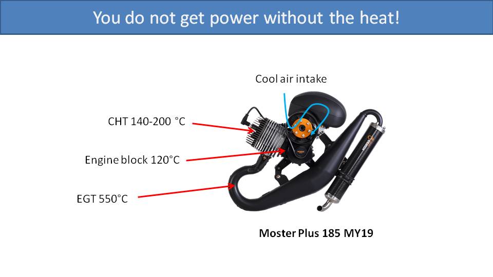
With internal combustion engines, you don’t get power without heat. The source of the heat is inside the cylinder where the combustion happens. So, the cylinder head is the hottest part of the engine. The fins on the outside of the cylinder head provide more surface area to dissipate that heat. The piston obviously absorbs a lot of heat as well. It’s cooled from within the crankshaft where fresh air is drawn in during the combustion cycle before it’s forced into the cylinder. Without cooling, the engine would quickly overheat and seize. Well-cooled engines allow us to use the most efficient and aggressive carburetor tunings. If cooling is so crucial, why don’t we use water cooling?
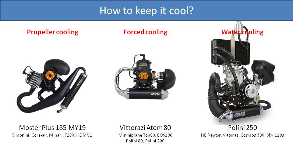
Let’s get into it. We have three typical options for cooling paramotor engines. The first is air cooling using the propeller. There are fins on the cylinder head and the propeller generates airflow across these fins to cool the engine. Next is forced air cooling. Here, the cylinder head is enclosed in a plastic or carbon fiber case. A fan, driven by the crankshaft, forces air through the enclosure and across the cooling fins on the cylinder head. In other words, it doesn’t rely on airflow from the propeller because it makes its own airflow with a fan. Finally, we have water cooling. Water surrounds the cylinder head and is connected by hoses to a radiator. A pump circulates the water between the two which efficiently cools the engine.
Water cooling is used for nearly all dirt bikes, but rarely on paramotors. The primary reasons are weight and simplicity. When designing a paramotor engine or frame, you start with the minimum features necessary, and then start testing. If those features are not enough, you add a little more, retest, and repeat. But you start with the minimum, which is propeller air cooling.
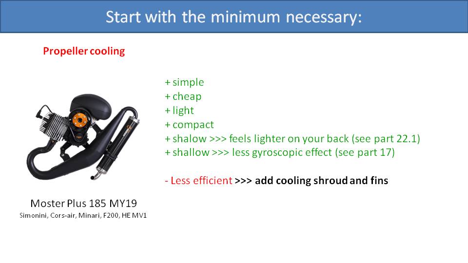
Propeller air cooling is simple. There aren’t any additional moving parts to fail. There are only the cooling fins on the cylinder head. So, fewer parts means that it’s cheaper and lighter. It also means that it’s more compact. A more compact engine allows for the propeller to be closer to your center of gravity which minimizes the gyroscopic effect. This also makes the engine feel lighter on your back, as well.
Propeller air cooling may be less efficient and less effective, though. So, we test it. If it’s not enough cooling, then we need to add some features to improve it. In this case we added a cooling shroud over the cylinder head and special flared fins on the propeller. Our cooling shroud is made of carbon fiber and wraps around the sides and top of the cylinder head. It guides the airflow from the propeller so that it pulls air through the fins on the cylinder head and doesn’t just go around. It’s also wider on the propeller’s side to draw more airflow from the propeller through the shroud. Then, on the propeller, a pronounced flare is added where it passes in front of the shroud. This flare is pointless for adding meaningful thrust to the propeller. However, it does increase the airflow in that area closer to the center of the propeller where the shroud is.
In our testing, we noticed that just adding the cooling shroud decreases the cylinder head temperature by an additional 20C to 25C. The cooling flares on the propeller did about the same, and together they decreased the cylinder head temperature by an additional 35C. So, adding those two features was a remarkable improvement to the propeller air cooling system. This technique is simple, light, cheap, and sufficient. As a result, it is often used on paramotors engines of this size.
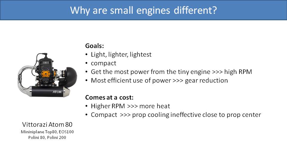
Smaller engines, like those that are 80cc, usually have forced air cooling. There are numerous reasons for this. First, it’s helpful to understand the primary goal of a small paramotor engine, which is weight savings. Pilots who choose smaller engines do so because they strongly desire a lighter paramotor. They are happy to do so at the expense of power, but they still usually wish it had more power. So, the designer tries to use all tools available to squeeze as much power as possible out of those little engines. They increase the top-end RPM, and they install gear reductions instead of belt reduction. The higher RPMs come at the host of higher heat, though. Also, with the more compact engine, the cylinder head is closer to the center of the propeller. There, the propeller does not generate enough airflow in that location to cool the engine. When you couple the higher heat and the lower airflow, this means you need to improve the cooling system for it to be sufficient. In this case, it means adding forced air cooling.
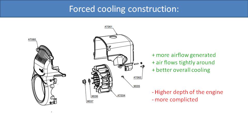
This is a schematic of the forced air cooling system of the Vittorazi Atom 80. There is a plastic case that encloses the cylinder head. It’s similar to the shroud on the propeller air cooling system, except it’s a full enclosure. Then there is a fan driven by the crankshaft. This fan blows air into the enclosure, over the cylinder head, and then out the vents on the back. This ensures a constant airflow across the cylinder head for maximum cooling. It’s the same principle as the propeller air cooled system, but improved.
This has some disadvantages, however. The first is the added complexity. This means more cost and more parts that may break. However, the bigger problem is that it adds depth to the engine. The fan must be inline with the crankshaft, and it can be quite big. So, the overall depth of the engine increases and it’s bulkier.
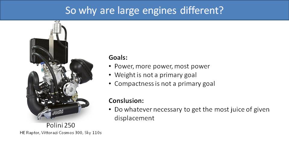
Let’s look at big, fat, powerful engines now. Why don’t these typically use forced air cooling? The primary goal of bigger engines is maximum power. Bigger engines are usually used for trikes, quads, and for slalom racing. In these cases, you want the most power possible at the expense of weight. Any slalom pilot would say, “Yeah, I would love it if my Polini 250 were lighter, but I can’t sacrifice any power. In fact, I want more power!” They would even accept a little more weight if it meant an additional three horsepower.
The same holds true with trikes and quads. Since they are on wheels, they don’t have to carry that extra weight on their backs. Once they load a passenger or two onto the trike, which already might weigh up to 50 kilograms itself, an extra couple of kilograms for water cooling is meaningless. They need extra power to get all that weight in the air and let them climb.
To maximize power on these engines, you increase the maximum RPM, the compression ratio, and the displacement. This all adds more heat, and you must cool it down efficiently. So, big paramotor engines rely on water cooling, just like dirt bikes. Water has a much higher “specific heat capacity” than air, so it is much more effective at cooling.
When looking at different engine sizes, their primary goals, and cooling choices, it’s interesting to see how paramotor engine designers all usually follow the same patterns:
· Small engines: forced air cooling
· Mid-sized engines: propeller air cooling
· Large engines: water cooling
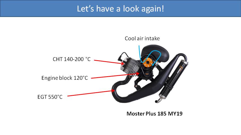
We’ve got one extra bonus topic relating to engine temperatures. If you have a Vittorazi Moster Plus, the cylinder head temperature usually operates at about 200C and the crankcase will be about 120C. The fuel-oil-air mixture enters the crankcase before being pushed into the cylinder. So, the temperature of the crankcase is very important for selecting the right 2-stroke oil and the right mix ratio. Many 2-stroke oils will start to evaporate at 120C, and vaporized oil does not lubricate. Mateo, the designer of the Vittorazi Moster Plus, explained to us why it is okay to use only a 60:1 (1.66%) ratio of Motul 800 instead of 40:1 (2.5%) for other oils. He said that at 120C, most 2-stroke oils evaporate into gas. So, the mixture must be higher to ensure enough liquid oil remains for lubrication. However, Motul 800 has a higher boiling point, so you need less of it to ensure proper lubrication.
Using a gear reduction is more efficient than a belt reduction, and yet most paramotor engines use belt reduction drives. Why so? There are some less obvious aspects of this decision. –Miro
Part 31.4: Gear Reduction vs. Belt Reduction
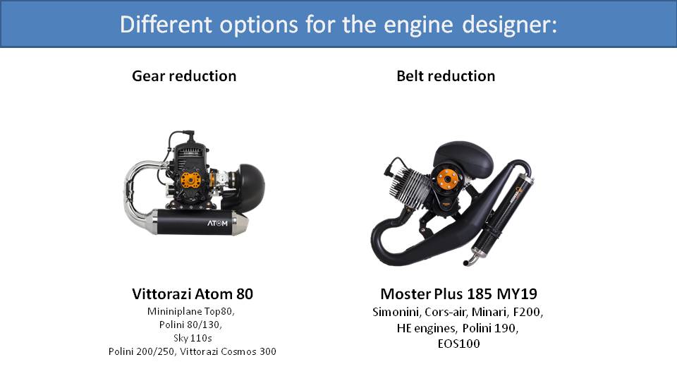
There are two options that paramotor designers use for reducing the speed of the engine to the appropriate speed for the propeller. These are gear reduction drives and belt reduction drives. On the left is a Vittorazi Atom 80, which uses a gear reduction drive. On the right is the Vittorazi Moster 185, which uses a belt reduction drive.
Beyond the Atom 80, there are many other engines that use a gear reduction drive like the Top 80 and Polini Thor 80. Note that these three examples are all small engines. But it’s curious that mid-sized engines all use belt reduction drives and then the really large engines, like the Polini Thor 250 and the Vittorazi Cosmos 300, go back to gear reduction drives.
This is an interesting pattern. There are reasons for this pattern, but some may be less obvious.
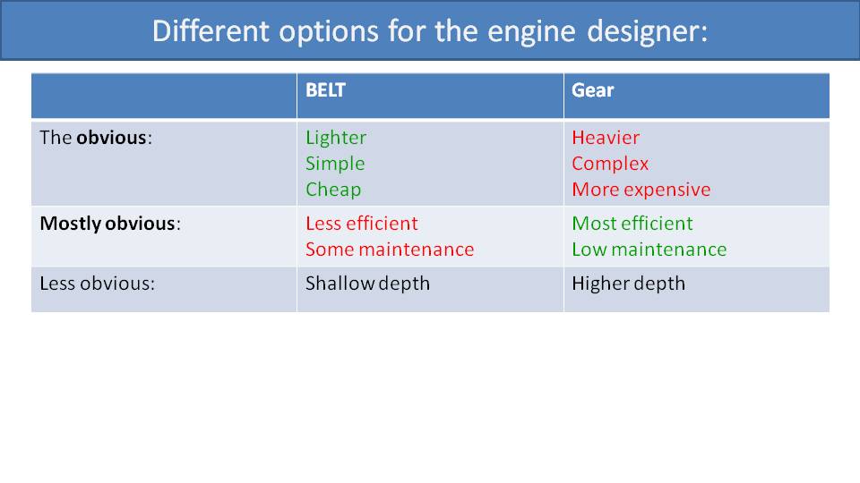
Let’s start with the obvious reasons. Belt reduction drives are simpler, which also makes them lighter and cheaper. Conversely, gear reduction drives are heavier, more complex, and more expensive. It may also be obvious to you that belt reduction drives are less efficient. This is because belts may slip a little as they heat up and will lose a bit of energy. They also require more maintenance as they often need to be retensioned and then replaced every 100 hours. It’s not difficult or expensive maintenance, but it must be done. Gear reduction drives are less trouble and more reliable, but you do need to change their oil.
What may not be obvious is that belt reduction drives are shallow in depth, and gear reduction drives are bulkier. This makes the engine deeper overall which pushes the propeller further away from your back. Let’s look at some drawings to understand this.
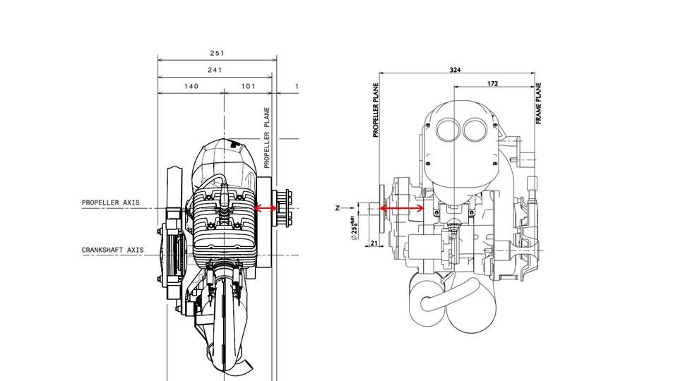
Here are two motors which are similar in size with different reduction drives. The Vittorazi Moster 185 is on the left and the Polini 200 is on the right. The overall depth on the Moster 185 is 251mm on the drawing. But, if you measure from the propeller plate to the engine mounts, its only 230mm. With the Polini, the distance between the propeller plate to the engine mounts is 324mm. Part of this extra depth is from the forced air cooling on the right side of the drawing, but it’s just as bulky on the left side, due to the gear reduction drive.
If we compare the lengths of the red arrows on each drawing it’s easy to see how much greater the depth of the gearbox on the right is than the belt and pulley drive on the left. On the belt reduction drive, the propeller just mounts directly on the large pulley. But the gearbox must have two gears with bearings on each side of them. The pulley on a belt reduction drive can have its bearings inside the pulley, which doesn’t add any depth. Then the gearbox must be enclosed for protection and to contain its oil, adding to its depth. In the end, the gear reduction drive is about twice as deep.
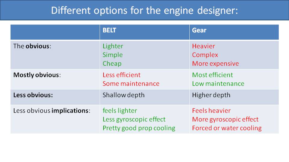
The implications of a deeper engine may not be immediately obvious. First, the further that the weight of your paramotor is from your back, the heavier it feels and the harder it is for you to walk with it on the ground. This is because the further back your center of gravity is, the more it will pull you backwards and you will have to lean forward to compensate.
Then, deeper engines have a stronger gyroscopic effect. In principle, the gyroscopic effect will be the same if the weight of the propeller and its speed are the same. However, the further away the propeller is from your back, the more leverage that gyroscopic effect has on your body.
Finally, engines with gear reduction drives must have forced-air cooling or water cooling, which further increases the weight. The cylinder head isn’t exposed enough with the extra gearbox to allow for propeller cooling.
When engine designers plan out a mid-range engine, they opt for the lighter and simpler system. Then they can use propeller air cooling and save weight on an engine that’s starting to get heavy. Smaller engines are already light enough, but they are short on horsepower. So, most engine designers opt to spend a little weight on a gear reduction drive to maximize horsepower. Finally, the biggest engines are used for trikes, quads, and slalom pilots. There, horsepower is also key, and the added weight of a gear reduction drive becomes worth it again.
It’s interesting to observe that most paramotor engine designers and manufacturers mount them the wrong way. –Miro
Part 31.5: Ideal Position of Engine Mounts
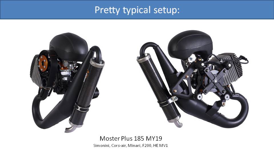
The Vittorazi Moster Plus 185 is the most popular mid-sized paramotor engine, but most other mid-sized engines have a similar overall design. The cylinder is off to the side and there is a belt reduction drive. On the front of the engine, with respect to the direction it travels through the air, there are four mounting points around the crankshaft. This is far from ideal, but most engine manufacturers still do it this way anyway. Let’s explain.
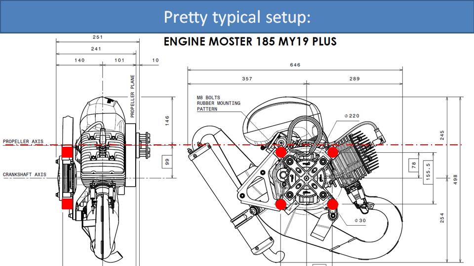
Here is a diagram of a Moster Plus 185 from the side and from the front. The big red dots are where the rubber mounts are that connect the engine to the frame. The dashed red line is the axis of the propeller, which is also the thrust line. You can quickly see that all four of the rubber mounts are below the thrust line. Let’s look at the diagram from the side to understand the implications.
Imagine what happens if you apply 75kg of thrust right on the dashed red line from the right side. This is quite a lot of force, much more than the weight of the engine. It’s like laying the front of the engine on the ground and then standing on the propeller hub. It seems that the engine designer didn’t consider this because the engine mounts aren’t inline with this force. What will happen is that the upper two rubber mounts will be compressed by all this force, and the lower two mounts will be stretched. The result is that the engine will tilt forward relative to the frame when adding thrust.
Because of this effect, the motor and propeller position within the cage is not the same when idling as when under full thrust. This is a problem that we must solve when designing paramotors. We designed the SCOUT such that the propeller sticks out from the cage more at the top than at the bottom. So, the propeller is not perfectly aligned with the cage while it’s sitting on the ground. Then, when you apply full power, the thrust makes the engine lean forward and squeeze into the cage to be perfectly aligned.
The engine designer decides where they place the rubber mounts. They could place the upper mounts above the thrust line to avoid this issue. But that would require them to extend the structural parts of the engine up near the airbox. That would add weight, cost, and other complications that they just don’t want to get into. The existing strong structural parts of the engine are right around the crankshaft, so that’s where they put the engine mounts. This is not just a knock on Vittorazi. Nearly all paramotor engine manufacturers that make engines in this size and configuration do the same thing. It’s not catastrophic by any means. We just need to install the engine with a bit of a tilt, which generates a few questions.
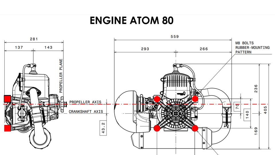
With small engines, the location of the engine mounts is better, yet it’s mostly a coincidence. The diagrams here are of the Vittorazi Atom 80, but the Top 80 is similar. In the picture on the right, you can see the crankshaft in the middle. The red dots show the locations of the engine mounts, which are placed symmetrically around the crankshaft. The propeller axis is just a bit higher than the crankshaft and within the engine mounts. Following the dashed lines of the propeller axis to the left, you can imagine that thrust from the propeller will compress all four engine mounts. The top mounts will be compressed a little more, but the bottom ones will also be compressed. So, with this design, any forward tilt under full thrust is insignificant. Vittorazi didn’t change anything with the motor design to specifically improve this behavior. Rather, due to the gear reduction drive being more compact, the propeller axis just happens to be closer to the crankshaft axis.
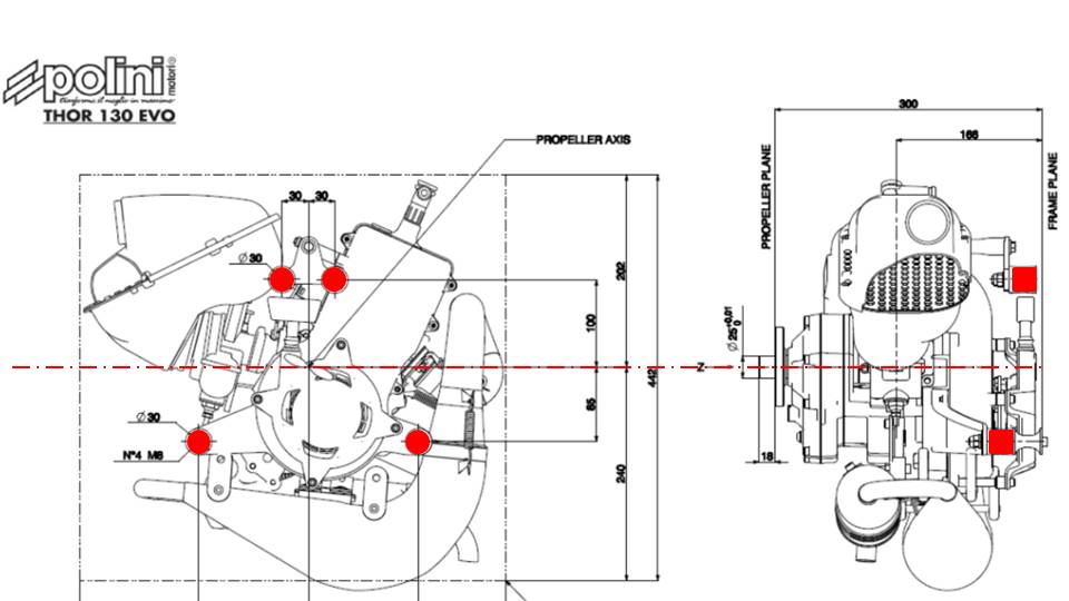
There is one paramotor engine manufacturer that does this well, however. This is a diagram of the Polini Thor 130, but their 190, 200, and 250 engines are similar. If we look at the picture on the left, we can see that they didn’t just place the engine mounts symmetrically around the crankshaft. They were able to place the mounts symmetrically around the thrust line. When you look at the engine from the side, you can imagine that thrust at the red dashed line would compress the red rubber engine mounts equally. They will be equally loaded, and the propeller won’t tilt at all on full thrust.
The reason that Polini can do this is because they use forced-air cooling for these engines. The other manufacturers use propeller air cooling and need to rotate the engine further away from the propeller axis to get the proper distance for cooling. At that point, they don’t have structural elements nearby to center the mounts around the thrust line. This is not a critique of one design or another, but rather just describing tradeoffs that engine and paramotor designers must make.
In this case, if you add forced air cooling to a mid-sized engine, it will add weight, cost, and complexity, but you’ll get more efficient cooling and better engine mount placement options. Otherwise, you’ll just have to describe to your friends why your propeller is tilted backwards while on the ground.
Fuel that is sitting on the ground is completely useless to you in the air. –Miro
Part 32: Fuel Capacity
[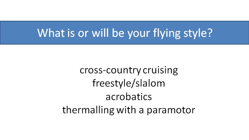
To help determine how much fuel capacity you want or how much fuel you should bring on your flight, let’s look at one of our earlier slides describing flying styles. Most pilots fall into the first category, cross-country cruising. This is the flying style that demands the most fuel, but it depends on your goals. Some pilots love to fly for a long time. Others like to fly fast to cover a lot of distance, which burns fuel faster. These pilots will obviously need more fuel capacity.
Freestyle and slalom pilots generally don’t need much fuel and can often get away with only two or three liters. Slalom pilots have very heavy engines and don’t want to carry unnecessary fuel.
Acrobatic pilots need enough fuel to climb high before killing their engine. This may only take a liter or two, so fuel capacity for them is also not an issue.
When thermalling with a paramotor, carrying three or four liters more than enough for an initial climb out, and leaves plenty of margin to climb if you miss a thermal or to help you fly back in the evening.
So, the flying style that demands the most fuel capacity is cross-country flying.
Obviously, having more fuel capacity doesn’t hurt, because you can always just fill the tank with the amount of fuel you want for that flight. But some countries, like the U.S., have restrictions on maximum fuel capacity.
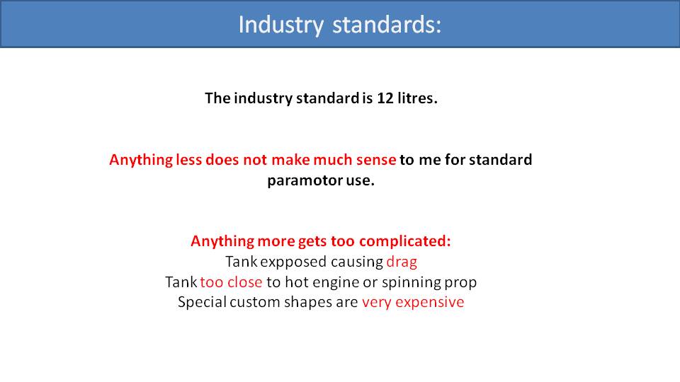
The industry standard for fuel capacity is around 12 liters. Most pilots consume between 3 and 5 liters per hour depending on their weight, speed, and flying style. So, a 12-liter tank can give you up to three or four hours of flying autonomy. Fuel tanks any smaller than that can be very limiting unless you’re just thermalling.
Fuel tanks larger than 12 liters get more complicated for paramotor designers. Depending on the engine size and shape, larger fuel tanks generally don’t fit very well. In the best case, they just stick out and create more drag regardless of how full they are. In the worst case, they get too close to the hot parts of the engine or the propeller causing serious safety concerns. This is why most paramotors manufacturers compromise at around 10 to 12 liters for their fuel tanks.
Paramotor designers could offer a larger fuel capacity with custom shaped tanks that maximize their usage of the space. But this customization means these tanks can be expensive. So, this leads us back to the 10-to-12-liter industry standard. However, some manufacturers offer larger tanks as a custom upgrade for those willing to accept the tradeoffs.
Weight is one of our favorite topics in paramotors, and yes, in most cases, lighter is better. –Miro
Part 33: Weight Matters
Obviously, the lighter a paramotor is on your back, the better. So, try to get the lightest paramotor possible for your needs.
Typical paramotors on the market weigh about 25 or 26kg, but there are ways to reduce this. Let’s talk about what you might be willing to chop off and sacrifice for weight reduction.
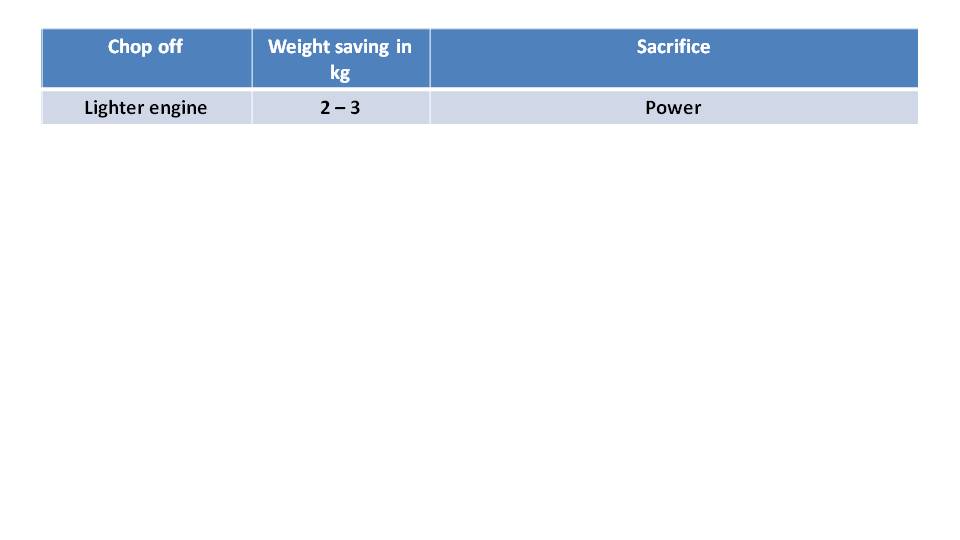
The engine is the heaviest part of a paramotor, so it’s the first place we look to save weight. In general, opting for a lighter engine sacrifices power. There are a few techniques to reduce the weight of an engine. The most straightforward is to reduce its size and displacement, which reduces its power output. Or you can build the engine out of thinner and lighter materials. Engine manufacturers already try to select lightweight materials and minimalistic designs, but aggressive optimization takes a lot of investment and can be expensive to manufacture. So, we appreciate any engine weight reductions that manufacturers make because it can take them a lot of time and money to do it. They know if they remove too much metal, parts overheat or break.
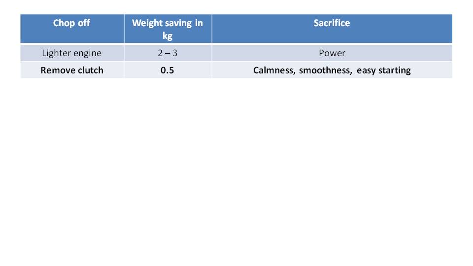
An easy way to reduce weight is to sacrifice the clutch. But we strongly prefer clutched engines and are happy to accept their weight.
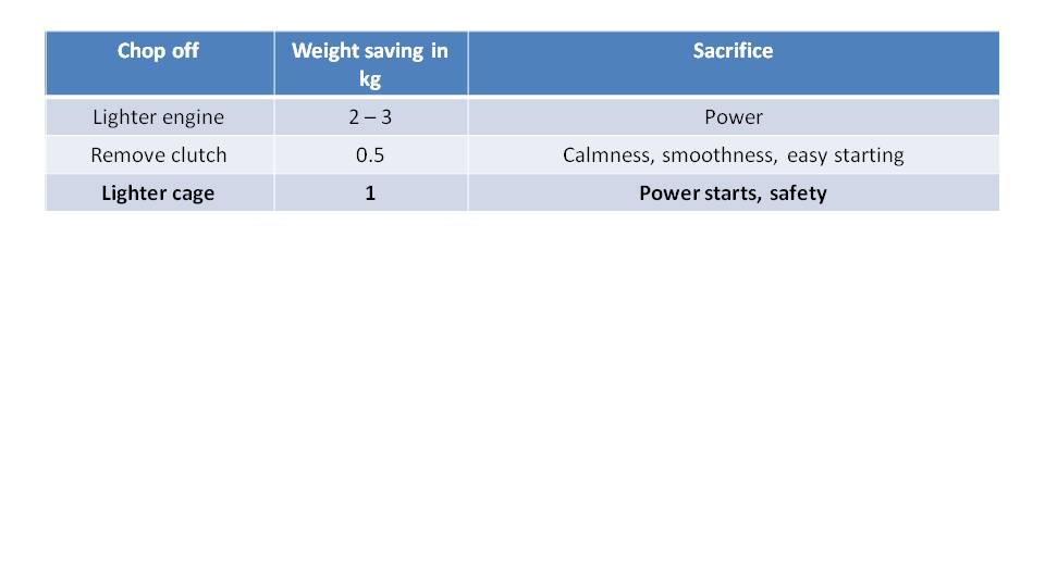
You can also reduce the weight of a paramotor with a lighter cage. A lower profile cage made with lighter materials will be lighter, but then the cage will flex more. A prime example of this is the Miniplane. It’s a great light design but comes with compromises. The cage is a bit flexible which is an issue doing a power forward launch. So, when pulling your wing up, you need to make sure the propeller isn’t spinning. Otherwise, as the cage flexes, it will strike the propeller. Hopefully, you just clip the tips off the propeller and don’t cut any lines. This is a perfectly acceptable tradeoff you might want to make as long as you are careful when launching.
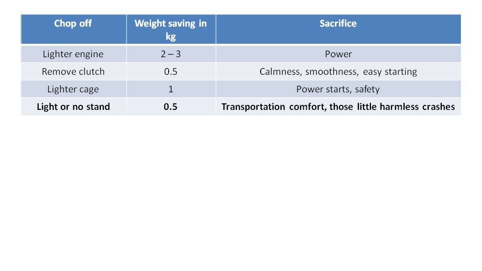
Minimizing or removing the stand at the bottom of the frame will reduce weight. On our first SCOUT, we had a light and minimal carbon fiber stand. Eventually, we added a proper full-size aluminum stand as a stronger option with added weight. Most customers chose this because the additional weight is not much. This stronger stand holds up much better when transporting the paramotor and can easily withstand the occasional butt landing without damage.
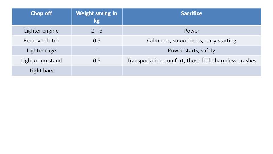
Another way to reduce weight is to use lighter suspension bars. We don’t feel this is a compromise worth making because it sacrifices your safety. These are the components that your life is suspended on, and it’s not worth making any tradeoffs. So, we designed the gooseneck suspension bars on the SCOUT to be CNC machined aircraft aluminum, so they are as light as possible without sacrificing safety. We also believe that paramotors should be load tested to ensure that the suspension bars and their hinges to the frame are safe to fly.

Instead of using lighter suspension bars, you could just remove them altogether. This would be a high-suspension system with just a strap and a carabiner. Then there is a spreader bar that ensures the strap keeps its shape, but this bar doesn’t need to carry the load of the pilot and the paramotor. This design certainly saves weight and is simple to manufacture, but we believe it takes away the fun and handling of the paramotor.
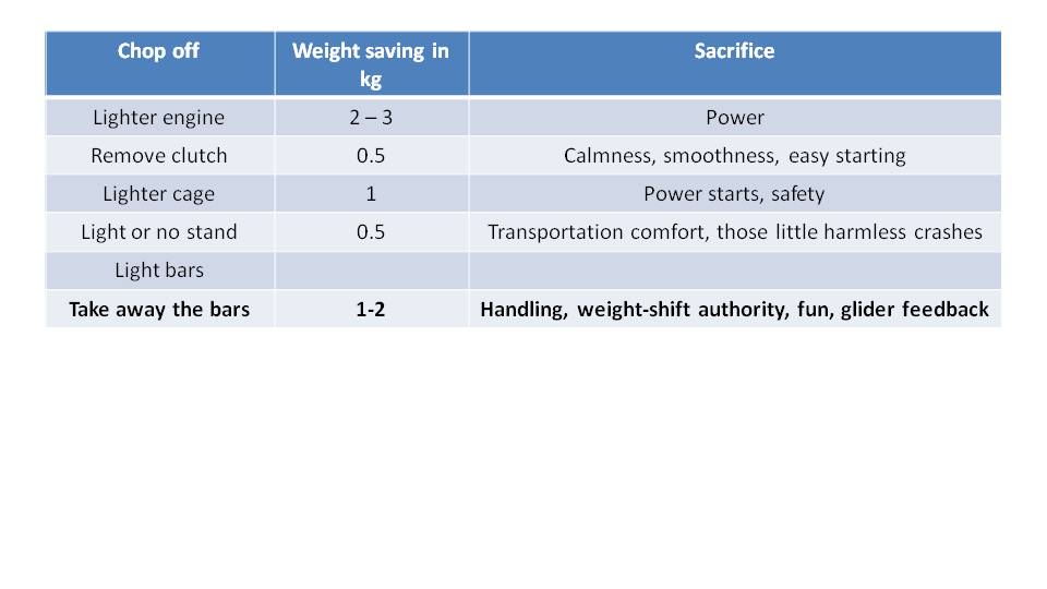
Not including an integrated reserve parachute container in the harness will save some weight. Many harnesses include an integrated pocket, pull handle and deployment tunnel. If you are fine with your reserve parachute on your lap, then this is unnecessary. But, then it’s a bit more of a hassle when preparing to take off to get your lap reserve hooked in. It can also be a safety concern if you have a water landing, and the reserve makes it difficult to free yourself.
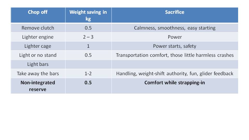
Another way to save some weight is to use a lightweight harness. Obviously, you can’t save weight with the internal structure of the harness, the straps inside the harness that give it its strength. But you can save weight with the type of fabric of the harness or by removing pockets. We did some experiments with lighter fabrics and were able to save about 1kg on the harness. It was great and just as comfortable but weighed less. But after a while, we noticed lots of wear and tear. The thinner fabric was just not durable enough for long term use.
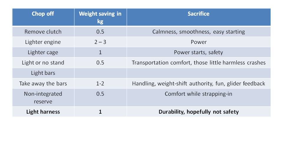
In total, there are ways to reduce up to 9kg of weight from a typical 27kg paramotor. You can get it down to 18kg or so with a smaller engine and a long list of compromises. So, you just need to figure out if any of those compromises are worth it for you.
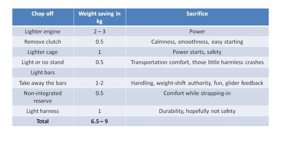
In aviation, everything is about aerodynamics. But it doesn’t seem to be that way with paramotors. Let’s discuss why. –Miro
Part 34: Aerodynamics
The main reason paramotor manufacturers don’t really care about aerodynamics, is that we fly slowly. They think aerodynamics don’t matter at these speeds. Honestly, this is nonsense and there is a strong proof of this…paraglider manufacturers.
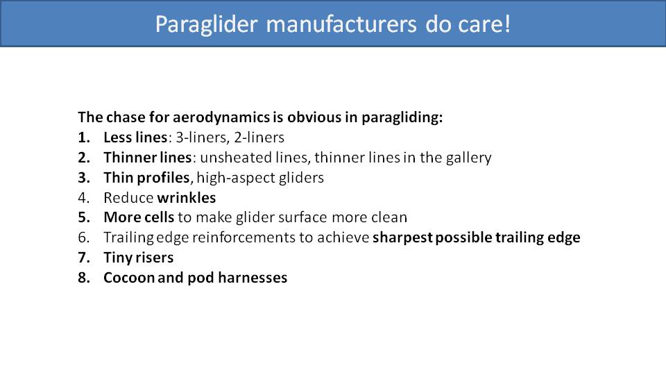
Paraglider manufacturers care greatly about aerodynamics. They are constantly trying to reduce drag to increase aerodynamic efficiency and lift. One of the most apparent things they do is to reduce the number of lines. First generation paragliders started with four or five rows of lines. These days, high-performance gliders cut this down to three, two and a half, or even two rows of lines. They are also reducing the number of lines per row. It’s amazing to see how few lines high performance gliders fly on.
Apart from that they are also using thinner and thinner lines. They will also use much thinner lines up in the gallery where the load is more distributed. Then, many high-performance gliders opt for lines without the protective sheathing which greatly reduces their drag.
Then, they offer high-performance gliders with thinner, more aerodynamic profiles and higher aspect ratios. They adjust manufacturing processes and laser cut the panels to reduce wrinkles caused by sewing the seams. They use more cells, so the surface is flatter and not as bubbly. All these improvements are to reduce drag.
Recently, they’ve been adding additional reinforcement ribs on the trailing edge. This makes the trailing edge sharper and cleaner to reduce drag on the backside of the airfoil. They also have all started using tiny riser systems, again to reduce drag. It’s amazing to watch them pay so much attention to the width of the riser and try to get it as thin as possible while keeping the required strength.
The other notable option to reduce drag when paragliding is using a pod harness. These beautiful harnesses are like kayak-shaped fabric cocoons that the pilot squeezes into to maximize aerodynamic efficiency.
This is a long list of proof that reducing drag has a remarkable effect on paragliders and how well they fly. This is how they increase the speed and efficiency of their flights to stay up longer and go further.
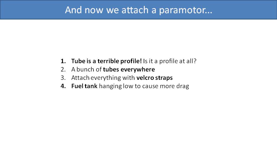
And now, here come the paramotor manufacturers who just weld a bunch of metal tubes together and send it. Tubes are horrible profiles in terms of drag. But, to make their cages strong and resilient to crashes, paramotor designers add a bunch of tubes and then fat Velcro straps to hold them together. Paraglider manufacturers fight to reduce the thickness of their lines from 0.4mm to 0.3mm and then the paramotor wraps a fat 2cm Velcro strap around some tubes. This causes a massive amount of drag.
Another example of paramotor manufacturers ignoring drag is by mounting a huge fuel tank way too low. These hang below the pilot directly in the airflow, causing an immense amount of drag.
We also must remember that the cage and the tank is not only affected by the drag of flying through the air, but also the drag of the accelerated airflow that the propeller is moving. So, all of these aerodynamic choices are exacerbated.
Unfortunately, paramotor manufacturers don’t have access to wind tunnels to measure this. However, there are ways to calculate drag using computer modelling to understand the effect of drag on their designs. But we can easily use the empirical evidence from paragliders to know that drag is very relevant for the speeds we fly at.
On top of this, today’s paramotor gliders aren’t that slow anymore. Many can fly over 60kph and some can reach up to 80kph or faster. These are speeds of small aircraft. Remembering that the force of aerodynamic drag increases with the square of the airspeed, this means that reducing drag is even more important the faster we fly.
Marcel Dassault, a leading French engineer and aircraft industrialist, said that in order for a plane to fly well, it has to be beautiful. In other words, if a shape is good for aerodynamics, it will be beautiful and you will like it. It’s just natural for us to appreciate it. If something looks aerodynamic, it will probably be aerodynamic.
Miro hadn’t heard this quote from Marcel Dassault when he started designing the SCOUT. He just started designing it to fly well without any compromises and it turned out to be beautiful.